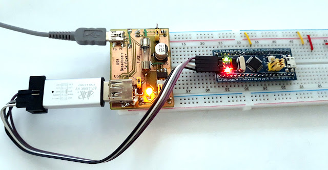
Build a fused power supply for breadboard that gets its power from the USB port and provides 5V at high current and 3.3V.
While trying to interface a gas sensor and a TV card tuner to an Arduino, I found that I had troubles powering them. Each of the mentioned devices need about 200mA. Both Arduino and the breadboard power supply use linear voltage regulators to provide 5V. I tried to use the breadboard power supply, but the regulator became hot immediately. Being fed with 12V, the 1117 regulator needed to dissipate (12 - 5) x 0.2 = 1.4 W. That's a lot for its small package.
I needed a better power supply. And I want it for breadboard projects. USB seems to be a pretty good power source, being able to provide at least 500mA. So I designed my own power supply. Since is USB powered, I thought it would be a good idea to have an USB port where I could plug development boards, without needing another computer USB port.
The mini USB is connected to the regular USB, so you can plug a development board, an USB to serial TTL adapter or a programmer straight in it. Therefore, this board features a working USB port, unlike the others. The power line is protected by a fuse. The same power line turns on an LED and provides power to the 3.3V regulator. You can switch from 5V to 3.3V by setting some jumpers, just as you do on common breadboard power supplies.
 |
| USB breadboard power supply schematic |
I designed two different PCBs. One of them uses the SMD linear regulator 1117-3.3, just as the schematic. The second one, is for a through hole regulator. You can use the LM3940 with a small heatsink on it.
 |
| PCB for USB breadboard supply |
Since I wanted to build the PCB myself, I designed it with one copper layer. Still, 4 wire jumpers are needed where tracks couldn't pass. The copper layer is on top of the board, for SMD components. If you build the PCB at home, without vias, some of the THT parts will be difficult to solder.
The PCB is designed in KiCAD and pinheaders for breadboard are aligned according to BREADBOARD_SPACING from SparkFun libraries (CC BY license). I realized that this footprint places pins a little more apart than the ones from Chinese MB102 power supply. Still, they fit on the breadboard.
 |
| Differences between MB102 supply |
Soldering top through hole parts to the top layer proved to be a challenge. You should make sure that no metallic undersides of parts touch the tracks. If this happens, you can place an insulator between part and PCB tracks.
Pinheaders are easy to solder. You have to push the pins through the black plastic holder, solder them and push back the holder.
 |
| Solder pinheaders on top layer |
 |
| Soldering USB connector on top layer |
 |
| Using the USB power supply for programming a STM32 board |
Downloads: KiCAD project.


No comments :
Post a Comment
Please read the comments policy before publishing your comment.