Showing posts with label Sensor. Show all posts

Gas detector based on MQ-2 without microcontroller

 Posted by:   Posted on:    No comments

Nowadays people are using microcontrollers even for blinking an LED. And that is no problem, since they are cheap enough, have low power consumption and are easy to program. But there was a time when microcontrollers were expensive and hard to find. And even then, engineers were building working devices, just smart enough to do the job they were designed for. Let's try to build a "microcontroller-less" gas detector using one of the MQ sensors.

Gas sensors from MQ family are analog tin dioxide detectors which change their resistance in the presence of volatile compounds like gases or smoke. Except MQ-7 and MQ-9 which are designed for carbon monoxide detection and require alternating heater voltage, with analog output being read at the end of each heater voltage cycle, every other sensor may be used in the following circuit.

Built analog gas detector with 3D printed enclosure

CO and LPG gas sensor with Arduino and LCD

 Posted by:   Posted on:    4 comments

In a previous post I looked at a MQ-9 sensor module. Unfortunately, although the sensor can detect CO and LPG, it cannot be used as it is wired in the module. After analyzing the datasheet I figured the best thing to do is remove it from existing PCB and build my own. In short, like other sensors from MQ family, MQ-9 has a heater resistor inside. In order to get any useful reading from it, this resistor must be heated at 5 V for 60 seconds, then cooled at 1.4 V for 90 seconds. The same is true for MQ-7. The issue with modules is that all sensors from MQ family are fitted on the same PCB design.

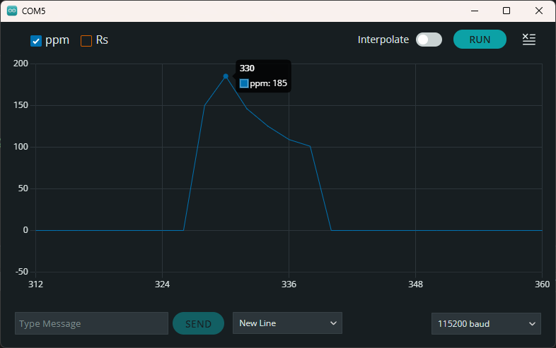
In this post, I'll share two other methods of powering the heater resistor and I will design a PCB. Sensor readings will be displayed on an alphanumeric LCD powered by Arduino. Since real ppm is temperature and humidity dependent, I will provide a PCB header for DHT sensor. I already tested the sensor with the LM317 power supply I built in the previous post, and I did some measurements.

CO and LPG gas sensor with Arduino and LCD

Influence of temperature and humidity on MQ gas sensors

 Posted by:   Posted on:    2 comments

I dedicated some of my previous posts to MQ gas sensors. These devices are cheap and can be bought on PCB modules, which implement a simple comparator circuit in order to provide a digital output. However, the usability of these modules is rather limited, knowing that some of the sensors from MQ family require variable heater voltage. More than this, at power-up the resistance of the sensor is low until the heater reaches working temperature, therefore the comparator output of a sensor module will trigger a false alarm.

Although this is not an important limitation, the modules do not take into account the variation of sensor resistance based on environment temperature and humidity. To do this, a microcontroller must sample the sensor resistance through an ADC and estimate gas concentration. This post continues a previous one in which I estimated gas ppm after extracting sensitivity data from datasheet graphs. However...

Influence of temperature and humidity on MQ gas sensors

Interface MQ gas sensor modules to 3.3V development boards

 Posted by:   Posted on:    No comments

Sensors from MQ family are tin dioxide smoke and gas detectors with analog output. Tin dioxide changes its resistance when exposed to gases, but it has to be heated. This is why these sensors have a heater resistor made of nichrome wire. MQ sensors are not suitable for battery powered devices since the heater requires a lot of current. In a previous post I took an MQ-2 module, changed some resistors on its PCB and interfaced it to Arduino.

Let's explore the possibilities of interfacing such modules to 3.3 V development boards. There are advantages like possibility of IoT integration, higher ADC resolution and more computing power on 32-bit architecture. There is however an... analog issue. When exposed to high concentrations of gas, the voltage across load resistor (RL) will go higher than 3.3 V. This could damage the ADC. We'll see in this post methods of scaling down the output voltage on load resistor.

MQ-2 readings with Raspberry Pi Pico

Compute ppm of MQ sensors from datasheet graphs

 Posted by:   Posted on:    No comments

I tried to connect some of the gas sensor modules I have bought over time to Arduino. Unfortunately, I discovered these modules were not designed properly and require some modifications in order to power sensors according to datasheet specifications. I am using an MQ-2 type sensor for this test and all of the following estimations will be specific for this type of sensor. You can use the same approach to read and process analog input of any of the other sensors from MQ family.

You won't find in any of the available datasheets a direct, clear formula to approximate ppm of a gas based on the sensor resistance. But there are some sensitivity graphs which we can use to find a correlation. To make things even more complicated, for MQ-2 there are two datasheets available, from different manufacturers, with different sensitivity data.

Compute ppm of MQ sensors from datasheet graphs

Attempts at reading data from MQ-2 gas sensor

 Posted by:   Posted on:    No comments

MQ-2 is a gas leakage detecting sensor with good sensitivity to a wide range of gases. Since you can get most MQ sensor on ready-made modules, people are interfacing those with development boards. However, the modules are far from perfect. Some of the sensors require variable heater voltages. This is not the case for MQ-2. Since I own a module with this sensor and it can probably be used as is, I decided to make some tests while I'm waiting a PCB for MQ-9 to be manufactured and shipped.

In the previous post I explained why modules with MQ-7 and MQ-9 are no good. Now, I'm about to discover the same for MQ-2. I thought I could use the module as is, since I am more interested in finding a method of computing useful data from the analog output of the sensor. With an Arduino compatible board and an MQ-2 module I will attempt to get ppm values. But not before some parts swapping.

MQ-2 test fixture, with sensor exposed to alcohol

Useless sensor modules based on MQ-7 and MQ-9

 Posted by:   Posted on:    No comments

When shopping for electronics parts and modules, I oftentimes add to cart things I didn't plan to buy, since most suppliers offer free shipping when total order amount is above a threshold. This was the case with a module I bought recently, a carbon monoxide and LPG detector based on MQ-9 sensor. When I got the time to build a breadboard circuit to test it, I came across a problem. As with most modules and devices, I started with MQ-9 datasheet. And at first I did not quite understand what they were saying about high and low heater voltage.

And the internet is full of examples regarding such modules interfaced to Arduino. And almost everybody seems to be powering it from 5 V, while some even developed code with advanced calculations to get real ppm value from the sensor. Throughout reading of the datasheets of both MQ-7 and MQ-9 reveals a "detail" almost everybody seems to have missed. In this post I will show you the correct way of using MQ carbon monoxide sensors. Keep in mind that CO and LPG are dangerous gases and if you need a detector, you should always buy a professionally manufactured one which is also properly calibrated.

Useless sensor modules based on MQ-7 and MQ-9
MQ-9 ready for testing

Air pressure, temperature and altitude with BMP280 sensor

 Posted by:   Posted on:    No comments

BMP280 is a digital air pressure sensor especially designed for mobile applications. It is a very small device, having a footprint of 2 by 2.5 millimeters. Interfacing with a development board would be difficult if breakout boards wouldn't exist. Even so, there's another issue: sensor's nominal voltage is 1.8 V. Fortunately, it can handle 3.3 volts. BMP280 can measure atmospheric pressure and temperature. Since there is a correlation between pressure and altitude, the latter can be estimated.

I ended up wiring this sensor to a 5 V development board because of the display. Pressure, temperature and altitude required 3 rows, so I used my ST7920 graphic LCD. Although this controller works at 3.3V, the way my display is hardwired by manufacturer does not because you cannot increase contrast enough. I connected the display in SPI mode, so only 4 wires are used (3 for SPI and 1 is reset). The BMP280 supports either SPI or I2C interface. Because the only level shifter I have is one I built a while ago for I2C, this is the protocol I wrote the code for.

The BMP280 sensor on the breadboard

The BMP280 sensor on the breadboard

Ultrasonic Tape Measure with HC-SR04 Sensor

 Posted by:   Posted on:    No comments
The wide availability and low price of microcontrollers makes it possible to update older analog designs to create reliable digital devices that are better and have more features. This time, using an ultrasonic sensor controlled by a microcontroller you can build an electronic distance calculator that can be used as an alternative to a tape measure for distances between 2 and 400 cm. I chose an ATmega development board (Arduino compatible) with an alphanumeric LCD to calculate and display data from the ultrasonic sensor.

The measuring device can be built entirely from ready made breakout boards and it can be powered from a 9V battery. With ATmega as its core, the device can have many features. The software supports current measurement hold and EEPROM storage. Stored measurement can be then displayed at a push of a button. The mode of operation is continuous. Measurements are performed each at 100 ms intervals and displayed on the LCD as long as the device is powered. You can pause the measurement by pressing the button assigned to HOLD function.

The device in the below photo can be built inside a case as long as the sensor's transmitter and receiver are passed through holes in the case. You will also need some holes for the display and buttons.

Ultrasonic Tape Measure with HC-SR04 Sensor

Measure RPM with Slotted Optical Switch

 Posted by:   Posted on:    No comments
Building an RPM counter is very easy with an optical switch and a way of counting pulses generated by the switch. A microcontroller, a frequency meter and even a logic analyzer can be used for this. Here, I will be using the cheapest and popular method: an Arduino. Optical switches are devices made of an emitter LED, usually infrared type and a receiver diode. Between the IR emitting LED and the receiver there is a slot. An opaque piece can pass through this slot and block IR beam. This will be detected by the receiver diode and its output will change state.

The piece that will block IR light will be a flange with a slot (a cutout area from the disc). When this passes through the switch's slot, the light reaches the receiver diode. Therefore, rotations are translated into a digital signal with a constant duty factor, dependant on flange configuration. The frequency of this signal needs to be measured and converted into RPM.

775 motor fitted with optical switch