How to read analog output from MQ sensor modules with ADC of 3.3 V development boards
Sensors from MQ family are tin dioxide smoke and gas detectors with analog output. Tin dioxide changes its resistance when exposed to gases, but it has to be heated. This is why these sensors have a heater resistor made of nichrome wire. MQ sensors are not suitable for battery powered devices since the heater requires a lot of current. In a previous post I took an MQ-2 module, changed some resistors on its PCB and interfaced it to Arduino.
Let's explore the possibilities of interfacing such modules to 3.3 V development boards. There are advantages like possibility of IoT integration, higher ADC resolution and more computing power on 32-bit architecture. There is however an... analog issue. When exposed to high concentrations of gas, the voltage across load resistor (RL) will go higher than 3.3 V. This could damage the ADC. We'll see in this post methods of scaling down the output voltage on load resistor.
In other words, this is just another issue caused by module circuit. We have a resistive voltage divider which we use to find sensor resistance. Why not power it from 3.3V (or the ADC reference voltage)? This would be the most straightforward approach, simple and reliable. But it is impossible since one pair of the sensing pins are hardwired to VCC. And VCC has to be 5 V for the heater.
 |
| Sensor wiring to ADC |
It is as simple as this. AREF is connected to 3.3 V or the reference voltage for ADC. VRL goes to ADC input. I am not going to modify one again the sensor module. Instead let's try to modify VRL to suit our needs.
I have around two development boards which are of interest. First is Wemos D1 mini based on ESP8266 with its wireless connectivity and 32-bit CPU looks promising, however the ADC is still 10-bit (as Arduino on ATmega328) and the maximum input voltage is 1 V. The second board is Raspberry Pi Pico W which has 12-bit ADC and integrated temperature sensor if you're thinking of sensor output correlation to environment parameters. Its ADC accepts a maximum of 3.3 V.
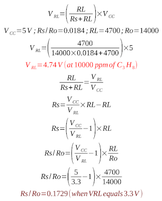
Refer to the linked previous post and to the datasheet of the sensor you are using. Same as before, I will be using the MQ-2 and refer to Winsen datasheet. In the worst case scenario, the lowest Rs/Ro is 0.0184 in 10000 ppm propane. This will result in the highest voltage drop across RL. Let's compute this voltage, as well as Rs/Ro ratio when output voltage is 3.3 V. With the sensor module, VCC has to be 5 V. I'll take RL = 4.7 k as it is on my module and Ro = 14 k.
Even with the unmodified module, with RL = 1 k, VRL is about 3.97 V in 10000 ppm propane. I also computed Rs/Ro when VRL reaches the maximum of 3.3 V. Now, using the equations from the previous posts, let's see what gases concentration can we read at 3.3 V:
 |
| Maximum ppm of gases when Rs/Ro equals 0.1729 |
Note that the above ppm values are estimated according to my sensor resistance, with RL = 4.7k, based on Winsen sensitivity data. The formula in ppm cells is: =POWER(Rs/Ro/Scale;1/Slope). If you are OK with these limits (given the fact that the lowest detectable ppm is 300 and the highest is the one from above table), you can use the sensor module as is. It is recommended to clamp the output with a 3.3 V Zener diode. Note that the upper limit of ppm would be somewhat higher with default RL = 1k.
Limited ppm range
Let's see the schematic. This will only work for Raspberry Pi Pico, where ADC can take up to 3.3 V. Nevertheless it can prove useful to trigger an alarm.
 |
| MQ-2 with Raspberry Pi Pico and clamped output |
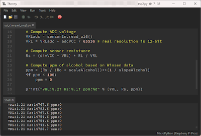
MicroPython code for this is slightly different. ADC reference is 3.3 V and we'll use this only to compute VRL at ADC input. Rs must be calculated considering the voltage divider Rs-RL is powered at 5 V.
from machine import Pin, ADC, Timer

tim = Timer()
sensorIn = ADC(27)

adcVCC = 3.3 # ADC reference
divVCC = 5.0 # voltage divider supply
RL = 4700.0
Ro = 14248.0 # presumed sensor resistance in clean air
slopeAlcohol = -0.552464627410705
scaleAlcohol = 10.2889924963885

def readSensor(timer):
    global sensorIn

    # Compute ADC voltage
    VRLadc = sensorIn.read_u16()
    VRL = VRLadc * adcVCC / 65536 # real resolution is 12-bit!

    # Compute sensor resistance
    Rs = (divVCC - VRL) * RL / VRL

    # Compute ppm of alcohol based on Winsen data
    ppm = (Rs / (Ro * scaleAlcohol))**(1 / slopeAlcohol)
    if ppm < 100:
        ppm = 0

    print("VRL:%.2f Rs:%.1f ppm:%d" % (VRL, Rs, ppm))


tim.init(freq=1, mode=Timer.PERIODIC, callback=readSensor)
The approach is a bit different, but most calculations are the same. I use a timer to read ADC every second. The output format is compatible with Arduino IDE Serial Plotter (while this code is executed on the Pico, you can open Arduino IDE, select Pico COM port and launch Serial Plotter).
Full ppm range
The method of clamping the output works with Raspberry Pi Pico. But it wouldn't work with Wemos D1 where you would have to clamp output to 1 V, which is totally useless. Here are some of the approaches to make analog voltage compatible:
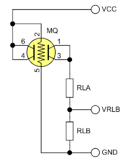
- Use a transistor buffer. The lowest VRL is in clean air. As long as this is above VBE of transistor, you can build a simple buffer with emitter resistor and feed emitter voltage to ADC. However, when computing Rs, you must add VBE to the voltage you measured to get the real VRL.
- Use an op-amp buffer then an attenuator. Get a rail-to-rail dual op-amp IC and power it at 5 V, same as MQ sensor. Use one unit to buffer VRL (VRL goes to non-inverting input; inverting input and output are connected), add a resistor divider at output of the first unit and buffer its voltage with the second unit. Overly complicated.
- Modify that module. Once again. Or remove the sensor from it and make your own PCB.
 |
| Sensor wiring with series RL |
Note that RLA+RLB should be within the datasheet recommendations for RL (for example, with ESP8266 ADC, RLA = 4.7k and RLB = 1.2k is a safe choice). It is worth mentioning the new Rs formula.
Anyway, I suggest you make completely separated circuits for heater and sensor if you get to the point of removing it from the module PCB.
Conclusion
Modules with MQ sensors are not quite designed for 3.3 V ADC. You can estimate low concentrations of gases if the ADC can't take more than 3.3 V, but be careful to add a clamping diode. As I said before, the best solution remains to extract the sensor from the module and build your own PCB with separate circuitry for heater and sensor.
Do not rely on a homemade device with this sensor to keep you safe. Always buy professionally manufactured gas and smoke detectors!


No comments :
Post a Comment
Please read the comments policy before publishing your comment.