LM317 power supply circuit with start from zero volts and additional supply for a panel meter or cooling fan.
An adjustable power supply is mandatory lab equipment for those who regularly deal with electronics circuits. One of the most popular integrated circuit for linear power supplies is LM317. There are countless power supply projects using LM317. This one has some additional features. The usual output voltage of LM317 cannot be lower than 1.25 V. However this circuit uses an additional negative power supply derived from the same transformer winding. With this, you can pull output voltage down to 0 V. The PCB also contains an additional power supply, with fixed regulator. Its purpose is to supply power to a custom made panel voltage and current meter. But you can use it to power a cooling fan if you want.

LM317 Power supply built PCB
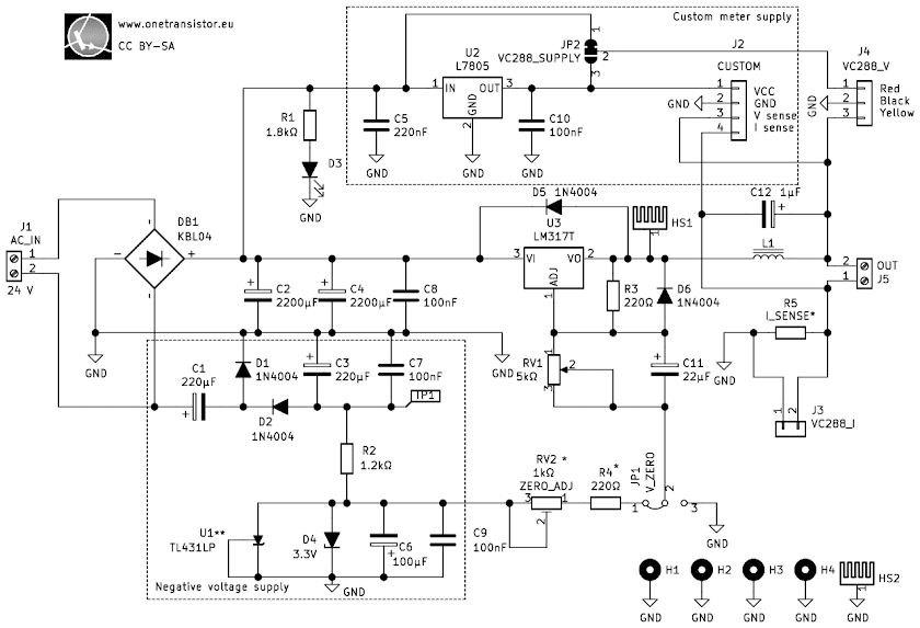
LM317 is a linear integrated voltage regulator with adjustable output. Although its maximum current is limited to 1.5 A, the device is widely used because this value is still enough for many circuits. LM317 uses an internal voltage reference of 1.25 V. Therefore the minimum output voltage is 1.25 V. There are rare situations when you may need less than that, yet this circuit is able to pull the output voltage down to 0 (zero) volts. This feature requires some additional parts and is available only if you use a mains transformer. Don't worry, the transformer should not have additional low voltage outputs. A negative voltage is derived from the same output that powers LM317, this voltage is regulated with a zener diode and fed to the voltage adjustment potentiometer. LM317 will output a voltage that is 1.25 V higher than the voltage present at ADJ pin. To get it to output less than 1.25 V, you must apply negative voltage to ADJ pin, no less than -1.25V. According to datasheet, the current through ADJ pin is no more than 0.1 mA. Since I used 220 ohms for R3, current through R3-RV1-R4-RV2 voltage divider is about 5.7 mA which adds to that 0.1 mA. Therefore a zener diode is suitable to regulate the negative voltage fed to this divider. Nevertheless, the option to have output voltages less than 1.25 V can be enabled or disabled with a jumper. If you choose the have it permanently disabled, the parts that make the negative power supply may not be fitted on the PCB. If you'll be using a mains SMPS (with DC output) instead of transformer, you can't have negative voltage.
The PCB comes with headers for common panel voltage and current meters. I'm talking about the DSN-VC288 digital voltmeter ammeter. Yet I was disappointed with the accuracy and update interval of those devices. They come with adjustment preset resistors, but there's nothing you can do since some of these meters are not linear. This means that you set the output voltage of the LM317 to a value, use your calibrated multimeter to measure it and then attempt to get VC288 to display the same value. Easy. But afterwards, you set the output voltage to another value and you notice VC288 shows different value than your multimeter. Same is true for current readings.
Since that's a big problem (my VC288 meter can display voltage with an error of 0.5 V) I decided to add an additional power supply on the same PCB. This one is still linear type, with a 7805 fixed regulator. Its purpose is to power any other digital panel meter. You can make your meter with an Arduino and display. VC288 includes a voltage regulator and can be powered with voltages as high as 35 V. If you are not sure this is true for the panel you bought, there's another jumper on the PCB that allows you to switch VC288 supply voltage from the higher unregulated DC to 5 V.
There is also the chance you bought a good quality VC288 meter and in this case you don't need a custom panel meter and its power supply. However, there could be another use for this power supply. Replace 7805 with 7812 and use it to power a cooling fan or whatever you want. But remember to keep current draw as low as possible. Because you're using a linear regulator, it will dissipate a lot of heat.

Schematic of LM317 versatile power supply
Board jumpers and connectors
- J1 (AC_IN): use a screw terminal to connect transformer secondary (output) winding. Maximum input voltage: 25 V AC, 37 V DC (if using DC output SMPS)
- J2 (CUSTOM): pinheader for a custom voltage and current meter. Pinout: 1 = VCC 5V, 2 = GND, 3 = output voltage, 4 = voltage drop on R5. If using a custom meter instead of DSN-VC288, fit R5 on the PCB. A 0.1 ohm, 1 W resistor will suit. At maximum current (1.5 A), the voltage drop on this resistor will be 0.15V with respect to the ground. This is the voltage you get at pin 4. Also, fit U2 voltage regulator to be able to power your meter.
- J3 (VC288_I): solder here the current wires from DSN-VC288. As long as this is connected, do not fit R5 on PCB. Respect the polarity (follow PCB silkscreen).
- J4 (VC288_V): power supply and voltage reading for DSN-VC288. Pinout: 1 = VCC (red wire), 2 = GND (black), 3 = voltage (yellow wire).
- J5 (OUT): screw terminal for power supply output.
- JP1 (V_ZERO): set lowest voltage to 0 V (1-2, enabled) or to 1.25 V (2-3, disabled). If disabled, parts C1, D1, D2, C3, C7, R2, U1, D4, C6, C9, RV2 and R4 may not be soldered on the PCB. They are of no use.
- JP2 (VC288_SUPPLY): DSN-VC288 can be powered with voltages up to 35 V, because it has its own regulator. If you set this jumper to 2-3 position, DSN-VC288 will get 5 V from U2. This means U2 must be mounted in this case.
Negative voltage supply
Negative voltage is derived from the same transformer winding. To regulate this voltage, you have multiple options.
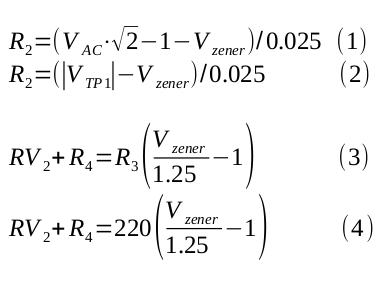
- With zener diode. That's what I'm using. It's D4. Do not mount U1. You'll get a negative voltage equal to zener voltage. R2 is biasing the diode and the value of 1.2 kilo-ohms is calculated for about 25 mA through a 3.3 V zener, assuming the unregulated voltage from transformer is 33 V DC (if transformer outputs 24 V AC). If you use a different transformer and/or zener, calculate R2 as follows: R2 = (|VTP1| - Vzener)/0.025. V(TP1) is the unregulated DC measured at test point 1, without minus sign. With 3.3 V negative supply, RV2 + R4 = 360 ohms. Feel free to use whatever component values you want for these two, as long as you can adjust their resistance near to 360 ohms.
- With TL431 you get 2.5 V negative voltage. TL431 supports a maximum current of 0.1 A. There's no need for that, 25-50 mA is enough. If using a transformer with a lower output voltage, adjust R2 too. Formula is similar: R2 = (|VTP1| - 2.5)/0.025. In this case, RV2 + R4 = 220 ohms for 0 V output. Do not mount D4 when using TL431!
- You can use TLV431? Well, no! Its maximum current is 20 mA and it is too low for this circuit.
This is how you can calculate R2 and (RV2+R4):

Replace Vzener with zener voltage for a diode and 2.5 V for TL431, respectively. When setting 0 V output, set main potentiometer to minimum (rotate to the left) and, while measuring output voltage, rotate RV2 to the right to go down to 0 V.
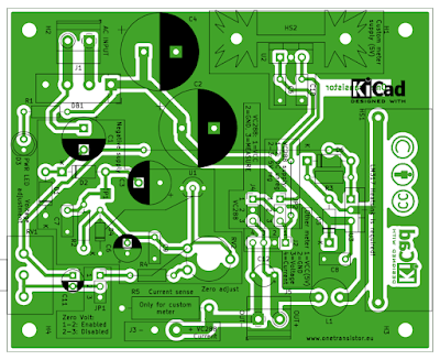
Here is the PCB layout. If you make your PCB at home, it is single sided and on top there are two wire connections. If you send the files to a manufacturing service, the two connections are made on the top copper layer.

PCB layout for LM317 power supply
Regarding the transformer, I highly recommend using a 24 V AC output at 3 A. In this way, you will get an output of 29 V maximum and the 1.5 A DC current can be supplied. The transformer can have 25 V AC output, but no more than that! Capacitors C1, C2, C3 and C4 should be rated for at least 35 V, although 40 V or 50 V would be a better choice.


No comments :
Post a Comment
Please read the comments policy before publishing your comment.