
Configure FreeCAD for CNC3018 and add milling tools to Path workbench library
I recently bought and assembled the CNC3018. I have never owned a CNC before and I was unpleasantly surprised by the lack of free and easy to use software to produce CNC jobs. So I had to learn FreeCAD, the only open source software known to me which can be used for this purpose. In this post I added the two types of tool bits supplied with the CNC to FreeCAD's library and I will attempt to produce various jobs in future posts.
CNC machining is a complex process and its workflow depends on a lot of interrelated parameters unknown to beginners. Setting them properly is an absolute requirement to complete a CNC job without breaking valid bits, ruining the work piece or damaging the machine.
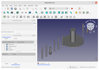
For the following setup I used FreeCAD version 0.19 (please use this version or newer because CNC tools library is different on previous versions). Start FreeCAD and make a new document (either click on the big plus button on the Documents tab in Start Page or choose New from File menu). Switch to Path workbench. There is no need to create an object in the document or to save the project when you will have to close FreeCAD. Once Path workbench has loaded, go to Preferences (from Edit menu).
General settings
In the General section, go to Units tab and make the following modifications:
- Unit system: Metric small parts & CNC (mm, mm/min)
- Number of decimals: 3
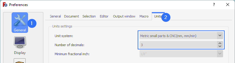 |
| Set units and decimals in FreeCAD |
Do not close the Preferences dialog yet. Switch to Path workbench preferences in the left sidebar. In Job Preferences tab, General section, clear any folder paths (FreeCAD will ask for these when we create the first toolbit library and a default installation comes with this path empty). Go to Post Processor section and let's create a default path for generated G-code files. If you don't know what to add here, enter %D/%d-%j.nc. This will tell FreeCAD to output G-code file in the same folder with project file. I used a fixed path for all my G-code files. I prefer to overwrite existing files so I can update/fix previous designs without being asked every time where to save the G-code file. Feel free to deselect all unused processors (maybe this will speed-up workbench loading) and select grbl as default one. Ignore any errors in FreeCAD Report View and click Apply. Basic settings are done.
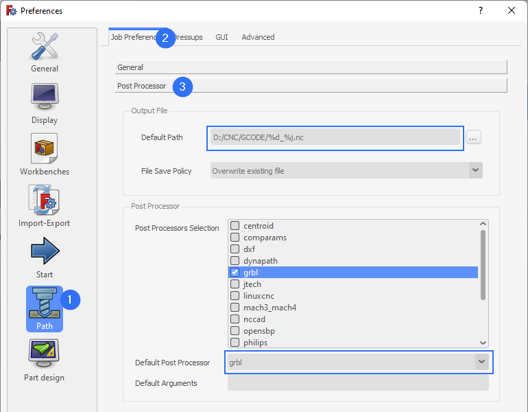 |
| Select CNC postprocessor in FreeCAD |
Toolbit library
Defining your own bits in FreeCAD is not quite straightforward, as you will go through a lot of open/save file dialogs and yes/no questions. Go to Path menu and choose ToolBit Library editor. It will ask you if you want to select a working directory where it will store custom libraries. Accept it and choose a writable folder of your choice (note that this folder can be copied to other device and imported in FreeCAD later or on another machine). Afterwards, it prompts you to create some subdirectories. Accept that. It will create Bit, Library and Shape directories.
Here comes one first issue. Next it asks whether to copy example library and bits to corresponding folder. This will only clutter your toolbit library folder however, if you say No to Copy example files to new Library directory? and no library is created, there will be some errors and the library editor will fail to open.
No worry though. Go once more to Path menu and choose ToolBit Library editor. This time it opens. The window which opens should have as title the path to Library folder you selected before.
 |
| FreeCAD Toolbit Library Editor window |
Click the middle button from the left to make a new library. Give it a name in the save dialog. I named it CNC3018. Do not change save folder (which should be the one from window title bar). Leave the dialog open.
The new library is empty, therefore you have to define toolbits. Here comes the next big issue. Click on Create Toolbit and you are prompted with an open file dialog. Yes, open not save. Because now it wants you to select the basic shape of the bit (which should be a FreeCAD fcstd document). I had no issue with this on Windows (it opens the dialog in the predefined shapes folder). Yet, on Linux it opens the file selection dialog in the Library folder (the one I created earlier).
Therefore you have two options: 1 - design your own bit or 2 - find the folder with predefined bits. I found that /usr/lib/freecad/Mod/Path/Tools/Shape/ is the default folder on Ubuntu with FreeCAD installed from deb package. What's an easy way to find it? Well, click the Default library (if you agreed to copy it to your folder) and edit one of its bits (double click on its name). You will see in the properties the full path to its shape.
 |
| Edit FreeCAD default bit to find shapes folder |
But what about creating your own bit shapes? In the folder you selected for your new library, there is a readme file. It summarizes also the steps to design your own bit shapes. However, I will not get into that now. Even you you choose to copy example library to your folder, the shapes will not get copied.
The rather surprising fact about bit definition, is that it does not hold the path to the shape, only file name.
{
  "version": 2,
  "name": "5mm Drill",
  "shape": "drill.fcstd",
  "parameter": {
    "Diameter": "5.0000 mm",
    "Length": "50.0000 mm",
    "TipAngle": "119.0000 \u00b0"
  },
  "attribute": {}
}
How do you start over again with this folder? Use the file explorer and delete it. Then, the next time you open ToolBit Library editor, it asks you to set the folder and you have to go over the same process again.
Below, when I say about creating bits, feel free to click Add Existing instead of creating a new one. Go to Bit folder from your library (one level up), select what you need and modify it accordingly. Note that any changes are reflected to all libraries which include this bit definition.
Bits supplied with CNC3018
With CNC3018 Pro kit I received two sets of 10 bits each, one with carving bits and the other with endmill bits. I will show you how to add both these types in FreeCAD. But, it is really necessary to set attributes for each toolbit? Well, FreeCAD wiki mentions this:
Most operations in Path workbench will return paths based on a standard endmill tool/bit only, regardless of the tool/bit type assigned in a given tool controller with the exception of the Engrave and 3D Surface operations.
Anyway it is best practice to have properly configured tool library. The problem is that I have absolutely no datasheet or documentation for these bits and I have to measure or approximate some parameters.
Carving bit
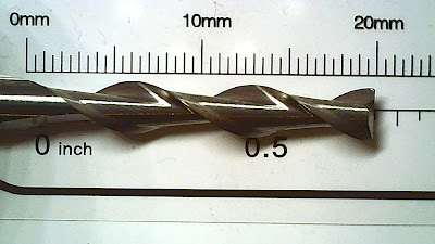
Click on Create Toolbit and choose the basic shape v-bit (browse to the path I talked about above). This is a parametric FreeCAD model of the toolbit. Next, bit attributes need to be saved in a file. As before, do not change save folder, just give it a name. I used vbit_25deg (because the tip of this bit has an angle of approximately 25 degrees).
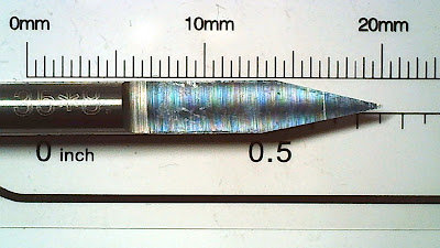 |
| Carving bit with 25 degrees tip angle |
Double click on the newly created entry to open its properties. If you double click on the tool number you can change only this number. Set the following:
- Shape
- Cutting Edge Angle: 25 °;
- Cutting Edge Height: 5 mm (not really needed);
- Diameter: 3.175 mm (not really needed);
- Length: 28 mm (not really needed);
- Shank Diameter: 3.175 mm (not really needed);
- Tip Diameter: 0.1 mm (presumably);
- Attributes
- Chipload: leave to 0; this is the theoretical length of material that is fed into the cutting edge when the bit advances through the material; it is proportional to feed rate;
- Flutes: 1;
- Material: HSS (presumably).
The cutting angle of the bit and tip diameter determine the carved line thickness, proportional to carving depth. These tool bits have some markings on them but no useful diameters can be read from those markings. Click on OK when you have set all parameters of this bit.
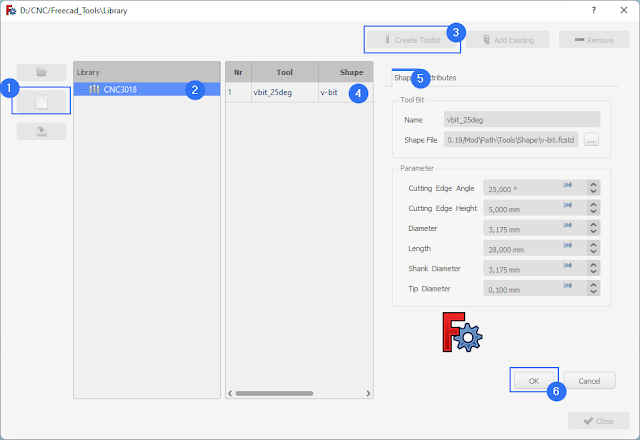 |
| Add Carving V-Bit to FreeCAD |
I tried to gather as much information as possible from everywhere I could. By looking in the sample G-code files of this CNC machine, they used 0.3 mm carving depth and 0.2 mm distance between subsequent passes when carving a surface. More on this later.
Endmill
Let's add this one too. In a similar way, click on Create Toolbit. Choose endmill model and save the new bit with a name (endmill_3mm). Set the following:
- Shape
- Cutting Edge Height: 15 mm (not really needed);
- Diameter: 3.175 mm (influences cutting width);
- Length: 38 mm (not really needed);
- Shank Diameter: 3.175 mm (not really needed);
- Attributes
- Chipload: leave to 0; this is the theoretical length of material that is fed into the cutting edge when the bit advances through the material; it is proportional to feed rate;
- Flutes: 2;
- Material: HSS (presumably).
 |
| 1/8" Endmill with 2 flutes |
Click OK and close the dialog window. Now, if you open the Toolbit Dock (toolbar button or Path menu) you will see CNC3018 library with two bits.
Other bits
Now you know how to add bits to FreeCAD. But do you know the available tool types?
- Ball end mills perform hemispherical cutting actions (a single pass produces a rounded bottom slot).
- Bull nose end mill is a type of end mill having a corner radius (this radius is a parameter requested when adding such a tool in FreeCAD).
- Chamfer cutters are used to clear sharp edges, leaving a sloped surface, or a chamfer, instead. These have the same parameters as V-bits.
- Drill represents the usual drill bit which can only cut in axial direction, with two flutes and a tip angle of 120°. This tip angle is editable in FreeCAD.
- End mill is different from a drill bit because it can cut in radial and (sometimes) axial directions. It leaves a flat bottom slot after a pass.
- Probe touches the workpiece with its tip, at different locations, in order to accurately determine the position of the workpiece.
- Slitting Saw is a circular saw. Blade thickness and diameter are specific parameters of this tool.
- Thread Mill is used to cut threads. This has many configurable parameters.
- V-Bit has a tip shape suitable for carving.
With CNC3018, you'll be using mostly V-bits for carving, end mills for cutting and regular drill bits for drilling holes (you are limited to special 1/8" shank diameter bits).
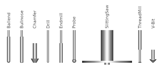 |
| Available milling tools in FreeCAD |
By now, you should have FreeCAD correctly configured for CNC milling and some tools added to the library. In the next post I will show you how to produce G-code for simple carving with the V-bit.


Thank you for this tutorial. It was very useful. At he end of it, you mentioned that the next tutorial would show how to produce G-code for simple carving with the V-bit. I cannot find the next tutorial. Has it been completed yet? I tired clicking the New Post button below several times but could not find it. Thank you.
ReplyDeleteNo, the next tutorial hasn't been yet completed.
DeletePlease, where can I find the next tutorial? And thanks for this one!
ReplyDeleteI'm sorry, but I haven't write the next tutorial yet. I found it very hard to produce G-code for carving with FreeCAD, especially when it comes to carving a surface. I will look further into this and hopefully publish a tutorial soon.
DeleteI look forward to seeing the next tutorial here. It eas really nice to follow a set of instructions where it was really clear where to click and what to ignore etc. Thanks!
ReplyDelete