30A MQTT relay with 4-digit time display powered by ESP8266 NodeMcu
I wanted to automate an irrigation pump, to be able to turn it on and off remotely and set a power-on time limit. I looked for a ready-made solution and I found some products. But none fit my needs. There are mains powered ESP8266 boards with one or more relays, but those relays are common 10A type. After some searching on AliExpress, I found an ESP8266 module with 30A relay, but this one was missing a mains adapter and required DC low voltage supply. This one could have been my choice. After all I only had to get a power supply.
Later, I decided to add a small display to my device so, I ended up making my own PCB. A NodeMcu board is the controller of this device. I added a 30A relay module and used a Hi-Link PCB power supply module to deliver required 5 V. The display is a 4-digit 7-segment TM1637 module which came with another challenge. It is a 5 V device that needs to be controlled by a 3.3 V MCU. I added a level shifter module and designed a PCB to fit all of them (except relay module which has its own PCB).
 |
| Electronics for the MQTT switch mounted in a plastic box |
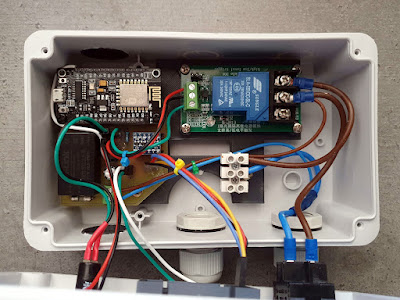
In the above photo you can see electronics mounted in a plastic wiring box, fitted on a back frame I 3D printed. Only one of the pin sides of NodeMcu inserts in the custom-made PCB. In the left (top and bottom) cable cutouts of the box, there are some 26 mm diameter ventilation caps with holes I 3D printed. The front panel contains a main switch, an on/off push button, the display and two LEDs. Display shows “OFF” when the relay is not triggered. Otherwise, it displays time in “HH:MM” format since the relay is on.
 |
| Front panel of the switch box |
The relay can be triggered using the front panel push button, with or without WiFi and MQTT broker connection. The software part will be the subject of a future post. Let's see how the connections are made inside the box.
 |
| Wiring of the modules |
NodeMcu is inserted on the custom PCB in a female pinheader and secured with M3 standoffs. Everything else is connected using wires, fitted with proper crimp terminals. Note there is also a voltage supply wire coming from the custom PCB +5V connector to NodeMcu VIN pin. Without this, the development board is not powered.
 |
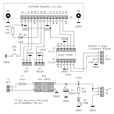
| Schematic for the custom made PCB |
The schematic is quite simple. A power supply and connection ports for all required modules. I opted to make the PCB at home using toner transfer method, because it is a single sided PCB with wide tracks, 61 by 55 mm board size.
 |
| The custom-made PCB of the MQTT switch |
There is not much to say here, except that instead of placing the two LEDs directly on PCB, I soldered pin headers and mounted LEDs on the front panel instead. The PCB has an unused 5 V output port and 3.3 V serial port (in case I want to add more peripherals, such as an extra controller with additional relays).
The not so well designed part of this project is that I have to remove everything from the plastic box to reach mounting holes. Even my back frame covers those holes. I will discuss the software in the next post (coming soon). For now let me show you the parts list and 3D models for the parts I printed.
Parts list:
- Surface mounted thermoplastic electric junction box, 110x110x70 mm, 1 pc.
- PG 13.5 Cable gland, 2 pcs.
- KCD4-201 31x25mm DPST rocker switch or equivalent, 1 pc.
- PS11BRD panel push button or equivalent, 1 pc.
- TM1637 4-digit 7-segment display module (pinheader must be unsoldered and placed on the other side of module PCB), 1 pc.
- 4-digit display panel mount with acrylic screen, 3D printed, 1 pc.
- Ventilation caps, 3D printed, 2 pcs.
- 5 mm LED panel mount, 3D printed, 2 pcs.
- Modules mounting frame, 3D printed, 1 pc.
- 30A relay module, 5 V supply, 1 pc.
- NodeMcu v3 ESP8266 development board, 1pc.
- Custom made PCB, 1 pc.
- 2.5 mm2 screw terminal block with 3-pole, 1pc.
- Screws, self-tapping, 4 pcs. for mounting frame, 4 pcs. for relay module, 1 pc. for custom PCB and 2 pcs. for terminal block.
- M3*12+6 standoff with M3*6 screw (nylon screws can be a good choice), 2 pcs.
- Low voltage side: wires and 2.54 mm male/female dupont connectors.
- Mains voltage side: spade crimp terminals and 2.5 mm2 wires.
 |
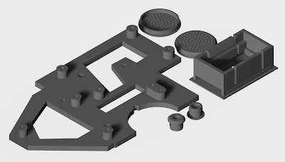
| 3D printed parts |
The ventilation caps are slightly larger than the 26 mm cable hole (I used a step drill bit for the large holes). Use some glue if needed to keep panel mounts in place. The back frame is screwed on the posterior face of the box (there are some standoffs on it).
With the exception of the back frame, everything is printed with default settings (PLA, 0.2 mm layer, 0.4 mm nozzle, sliced in Cura for Artillery Genius Pro). I don't need too much quality for the back frame so, I used 0.28 mm layer to speed up the print. I should have made those holes in ventilation caps larger in diameter (they are 2.4 mm), but they are still printed even at this small size.
Downloads:
- KiCad project with Gerber files, ready to upload to a PCB manufacturer.
- Models for 3D printed parts are available on Thingiverse.


No comments :
Post a Comment
Please read the comments policy before publishing your comment.