Install the drivers and use the included software to read and write memory chips with the EZP2023+ programmer. Software download links at the end.
Previously I analyzed the hardware of EZP2023+ USB Programmer to find it is a rather simple device, based on CH552G microcontroller which allows for SPI, I2C and MicroWire capabilities. If you didn't know this is a serial memory programmer, which can be used to read and write a variety of memory chips, including EEPROMs and BIOS ICs commonly found in computers and other electronic devices. After I traced the schematic, I realized EZP2023+ also comes with mixed voltage levels (meaning it powers the memory to program with 3.3 V while the data bus uses 5 V for I/O) and this is a big issue since it can destroy whatever you are trying to read or program.
In this post I will share my experience with the programmer and discover some flaws of its programming software. You should get the programming utility on a CD which is in the product box. Since recent computers and notebooks no longer have an optical drive, this is already an issue. Getting past that, on the CD you will find the user manual and accompanying software, with driver. Let's see how you get everything ready to program memory chips.
Quick how-to
One will need this programmer to read and write EEPROM and FLASH memory chips in various electronic devices to reset, update or fix corrupted firmware. Although you can get an in-circuit programming clip, it is highly advisable to unsolder or remove the memory from its host device to avoid any issues. Applying power to the chip while it is in-circuit may also supply other stuff with a limited current (CPU or other peripherals) potentially causing damage.- Plug the programmer into the USB port of a Windows computer with no memory chip placed in socket.
- Install driver as I will show you below.
- Disconnect from USB.
- Place a memory IC in the programmer, directly or via an adapter. See my previous post about chip placement.
- Launch programming utility and change language to English.
- Plug the programmer into the USB port.
- The state displayed on the status bar of the programming utility will change from "Not connected" to "Ready".
- Use "Test" button to detect IC or select it from the list.
- Perform read, write or erase operations as needed.
- Unplug from USB when done.
Driver
First of all, the programmer needs a driver. There are some provided, however there is no need to worry if those do not work, because they are actually libusb based and you can always generate a driver with Zadig.
Please note that according to user manual, when you plug in the programmer it can appear in Device Manager as "usb programmer device" or as "WinUSBComm". Mine appears as latter and has IDs 1FC8:310B and for this I can confirm this method works. Be very careful what device you select. A wrong selection will replace the driver of another USB device causing it to stop working.
Here is what I selected in Zadig (the correct device and libusb-win32):
 |
| Install EZP2023+ driver with Zadig |
Software
Once you are done with this, launch the programming utility. It is a portable executable, Windows only application which looks a bit... old. If it displays strange characters, click the fifth item in the top menu bar (which is language) and choose the third item in the submenu, named "Enlish", while ignoring the missing "g". Close and reopen if display issues persist. Check the status bar; next to state it should display Ready if the programmer is connected to a USB port.
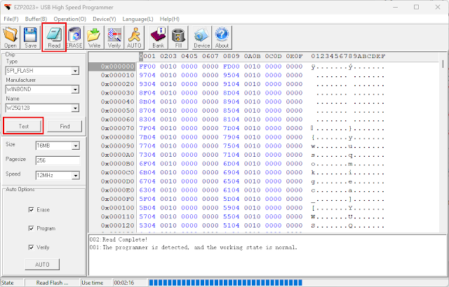
Chip placement is explained in the previous post. If you have a SPI memory in the programmer, you can click Test to auto detect it. If this fails or you have I2C or MicroWire, use the combo boxes or the Find button in the left pane to find your IC or something equivalent. If it can autodetect it, the relevant selections will be made automatically. At this point all you have to do is click Read from the top toolbar.
 |
| Reading SPI FLASH with EZP2023+ |
It is as simple as this. Performing other operations (write, erase) is intuitive. You can edit the database of known devices if you click Device button from top toolbar. You'll be prompted with a table of chips and its column headers will not be in English (or whatever you selected earlier), but you'll figure out what they mean based on existing entries.
Clock speed
Now, I can't end this post here. There is a speed selection in the left pane. Since I am curious I did reading tests on the same flash memory (the poor chip survived at 5 V I/O) and populated a table of read times (note that I recorded the use time displayed in the status bar of the programming utility). Even more, I placed an oscilloscope probe on the serial clock line.
The flash chip is W25Q128 with 16 megabytes of storage. In comparison, an unmodified CH341A MiniProgrammer reads this chip in 02:18 with AsProgrammer at a maximum clock speed of 1.7 MHz. Here are the results:
| Speed selection | Measured clock frequency | Memory read time |
|---|---|---|
| 12 MHz | 12 MHz | 02:16 |
| 6 MHz | 8 MHz | 02:20 |
| 3 MHz | 6 MHz | 02:28 |
| 1.5 MHz | 4.8 MHz | 02:33 |
| 750 kHz | 4 MHz | 02:37 |
| 375 kHz | 3.5 MHz | 02:45 |
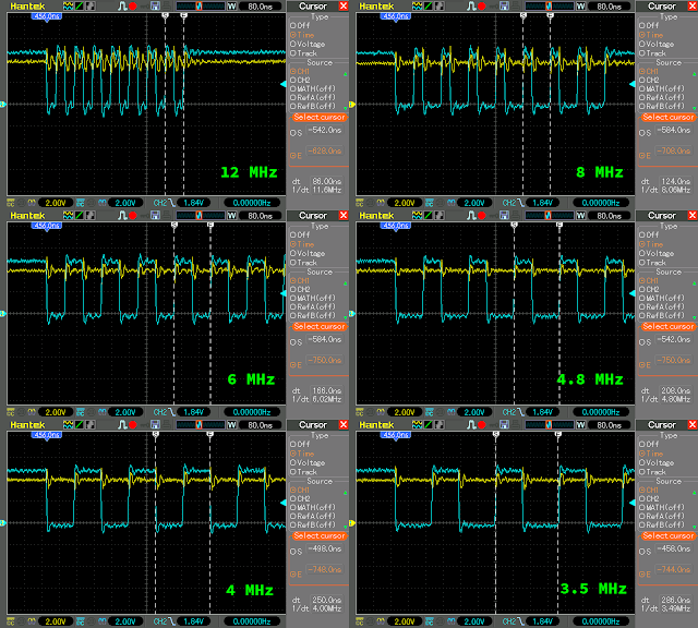
And here is how the clock looks like. Ignore the distorted signal with wobbly states (I used some hookup wires with clips to SCK pin of the SMD adapter). It is quite clear that all lower frequencies are derived from the 12 MHz one.
 |
| SPI Clock captures of EZP2023+ at different speeds |
Because of this, the 8 MHz clock has 33% duty cycle, the 4.8 MHz one has 40% and the 3.5 MHz has 43% duty cycle. Knowing that the only clock frequencies with 50% duty cycle are 12, 6 and 4 MHz, you can choose them from the programming utility (speed): 12 MHz, 3 MHz and 750 kHz. It is worth noting that in the screenshot from user manual, they only have 12 MHz, 6 MHz and 3 MHz in the list (probably a different version of the programming utility).
Overview
EZP2023+ can only be used on Windows, since there is no programming utility for other operating systems.
Clock speed selection is a nice feature, it is something that CH341A doesn't have, however it is worth mentioning not all available speeds produce a clock with 50% duty cycle and the frequency you select in software doesn't match the hardware. This shouldn't cause any issues with most memory ICs.
With I2C EEPROMs there is not much to say. I2C clock speed is limited by protocol and both CH341A and EZP2023+ seem to read a 24C32 memory in slightly over a second. The speed selection box remains active in the programming utility even in I2C mode but it doesn't make any difference.
CH341A or EZP2023+? Get what fits your needs keeping in mind that both of them have the mixed voltage levels issue but the CH341A is cheaper and there is a fix for that issue.
Software and manual download: EZP2023+ ver3.0 (this is the CD content for those who don't have optical disc drive).


Tengo un problema para instalar los drivers del ezp2023 en mi laptop con Windows 10 me da un error 43 cuando mando actualizar los drivers
ReplyDeleteEL0VRRGA
Delete