Build this versatile, yet simple serial port sniffer to debug and take over communication between two devices
A serial port complying with the RS-232 standard was once a standard feature of many types of computers. Today, RS-232 has mostly been replaced in personal computers by USB for local communications which allows for faster speeds and is easier to connect and use. Despite this, the protocol used by RS-232 is still in use today, on various devices, ranging from microcontrollers to embedded systems and even computers. The original voltage levels (ranging from -15 to +15 V) have been replaced with platform specific levels (from 0 to 2.5 V, 3.3 V or 5 V). The serial port is no longer found in its original shape and pinout. Nowadays, mostly Rx and Tx signal lines are used.
There are times when serial communication needs debugging. You may use a logic analyzer to check the bitstream and determine its baudrate and if that's present, the next step is to view or record what's being sent over the port. The sniffer I will show you here is able to intercept serial communication and disable Tx lines in order to inject its own data. Since most modern devices do not use auxiliary lines, the circuit shown here is able to monitor only a single pair of Rx and Tx lines.

Hardware
Since most devices that still have this port use TTL voltage levels, the schematic I will show you is compatible with 3.3 V and 5 V levels.

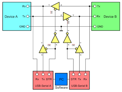
Functional schematic of serial port monitor/sniffer
Let me explain how does it work. The device is inserted between two other devices using UART serial communication. A computer with two USB-Serial adapters is required. Anything can be used for this (FT232, CH340G, PL2303, CP2102). By default, Tx line of Device A is routed to Rx of USB adapter A. The Tx line of the Device B is routed to the Rx of the other USB adapter, B. Now, this is what most users require. You can now monitor data streams, without interfering with communication between the devices. Data sent by Device A is captured by USB adapter A, while data sent by Device B is captured by USB adapter B.
Yet, this circuit comes with additional features. USB adapter A is able to send data to Device A. Same is true for the other side. To do so, it must set DTR low. DTR, an additional signal of the serial port is idle high. In this mode, the buffer on Tx of the USB adapter is disabled and the buffer between devices is enabled, allowing normal communication. When DTR is set it goes low. Two things happen: the normal communication line is disabled because the corresponding buffer gets disabled; and the device is now able to receive data from the corresponding USB adapter since its buffer just got enabled. When one of the USB serial adapters is taking over communication - let's assume here that USB adapter A did it - if Device B sends something it never reaches Device A, but you can see what it has sent in the terminal of USB adapter B.
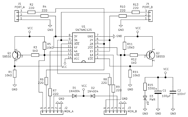
The takeover functionality is available only if the USB Serial adapter you're using has a DTR line that you can set from software. That's why I recommend FT232 breakout boards. The complete schematic is the following. Pinouts for MON_A and MON_B are suitable for FT232 adapters.

Hardware serial port monitor schematic
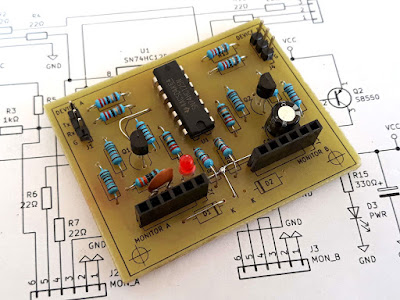
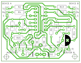
The only IC used by this device is 74HC125. It was easy for me to find SN74HC125 in a local store although they are obsolete and have been replaced by SMD variants 74LVC125A. To avoid the voltage drop across diodes, you can remove both and use a jumper wire in the place of one of them (as I did). In this way, the circuit gets its power from one of the USB-Serial adapters only. The practical build requires a single sided PCB, 57 by 44 mm.

PCB of serial monitor
Note that the pins of device ports should be connected directly to corresponding devices (for example Rx of this circuit must go to Rx of the device). Pinouts for Monitor A and B correspond to FT232 breakout boards which should be plugged into pinheaders with the ground on the right. You can download KiCad schematic and PCB project here.
Software
The first thing that comes to mind is some kind of software to monitor serial ports. Such tools do exist, but they work in a different manner: they expect the port to be opened by another application in order to display port traffic. That's what you use when you monitor traffic between a device and the computer you're running this software on.
Since the hardware monitor is inserted between two devices, on the computer (which becomes the third device), you get two serial ports on which you can see data from monitored devices. In this situation, you need a serial port terminal. With its ability to open multiple ports at a time and different data views, I prefer Advanced Serial Port Terminal from Eltima. They also develop products for monitoring serial ports.
It's easy to use. When you plug the USB-Serial adapters from the described device, two new serial ports appear on your computer. All you have to do is open both of them in Advanced Serial Port Terminal. The bad part here is that you must know the baudrate. You can open and close the port anytime you want, without closing its terminal session. For now, check Open port at once. Repeat for the other port.

Port settings
Once you've opened both ports and the devices you're monitoring are exchanging data, you'll start receiving it. Each port corresponds to one device. If you want to send, you must break normal communication. Make sure you're on the correct tab and set DTR (click on DTR and make sure it is green). When DTR is set (green), the logic level is LOW and Tx of your adapter is connected to Rx of the device.
So, for normal communication, DTR of both ports should not be set (red). Otherwise, clicking on it changes its state to green and during this setting you can write to device.

Advanced Serial Port Terminal main window
Advanced Serial Port Terminal is not free, but you can request a free single license here. It would have been nice if you could see both ports on screen, as tiled windows, instead of tabs. Depending on your needs, you may even use this device with a single USB-Serial adapter.


No comments :
Post a Comment
Please read the comments policy before publishing your comment.