Install official support for STM32 bluepill on Arduino IDE and start programming and uploading sketches with STM32CubeProgrammer
Back when I wrote Set up STM32 "blue pill" for Arduino IDE I found two Arduino Boards packages for STM32. I didn't know at that time what were the differences between them and that post uses the STM32 package developed by Roger Clark. In fact, that one originates from libmaple which was first developed by LeafLabs for their Maple boards. The library was written in 2012 and it is no longer under active development.
I consider STM32duino to be a better alternative now, since it is actively developed by STMicroelectronics and uses as backend recent versions of STM32 libraries (LL, HAL). More than that it has support for multiple cores and boards including, but not limited to, official evaluation boards, 3D printer boards and flight controllers. To be able to use it you need a board and a programmer, Arduino IDE and STM32CubeProgramer. Fortunately the required software is cross-platform so you can code for STM32 on any platform. In this post I'll show you how to install the required software and how to upload sketches to STM32 "blue pill".
Hardware
Board
This post is about STM32 "blue pill" which is a development board based on STM32F103C, with 64 or 128 kB of flash memory. It has an USB port but there are some issues with a pullup resistor. USB D+ is pulled up with R10, which you can find on the back side of the board PCB. If it is not 1.5 k (marked 152) then it may cause troubles when using the USB port. If you have the proper tools, replace it with a similar SMD resistor of 1.5 k. Otherwise, use whatever soldering tool you have and solder a resistor (R*) between pin PA12 and 3.3V. The value of this resistor should be chosen as to get an equivalent resistance of about 1.5 k with the existent R10. R10 is commonly 4.7 k (472) or 10 k (103). Then the resistor (R*) you will solder should be 2.2 k or 1.8 k, respectively.
Make sure the USB connector is properly soldered. Some boards have this problem. Note the LED pin (PC13 usually).
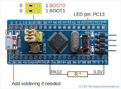
Blue pill hardware check
Programmer
There are multiple options here. Even the Maple USB bootloader is supported. A popular programming mode is with a USB-Serial adapter. This is possible because STM32 MCUs have an integrated bootloader that handles serial port to flash data transfer. This bootloader is activated by setting BOOT0 jumper to 1. I hate to do this every time I upload binary to flash.
It is very easy to program "blue pill" with ST-Link programmer and even clones do the job. The programmer handles the reset of the board without any user interaction. So, if you haven't yet, get a ST-Link programmer. It connects to the board using 3 or 4 wires (GND, SWCLK, SWDIO). Only if the board is not otherwise powered (from USB port!) connect the 3.3V supply from programmer.

STM32 bluepill connections to ST-Link programmer
When it needs to reset the MCU, the programmer can issue a software reset command. You have the option, by adding an additional wire from programmer's RST pin to board's R pin, to trigger a hardware reset. This additional wire is not needed when uploading from Arduino IDE.
Software
Programmer
There was once STM32 ST-LINK Utility, a Windows only tool for ST-Link programmers. Now, there is STM32CubeProgrammer, a cross-platform Java based programming utility. You have to provide e-mail address to download software from ST.
- Windows users will download and install latest Oracle Java JRE.
- Linux users must have OpenJDK or Oracle Java installed to run the graphical installer. Arduino IDE uses for upload the command line programming utility which does not require Java to run. If you want to run the graphical interface of the programming software you have the option to install openjdk-8-jre-headless and openjfx=8u161-b12-1ubuntu2 libopenjfx-jni=8u161-b12-1ubuntu2 libopenjfx-java=8u161-b12-1ubuntu2. See UM2237 for more information. Or you can replace OpenJDK with Oracle Java. I chose the second option since it made other Java applications run and I don't depend on a specific version that may get outdated and no longer maintained with new releases. Run the installer as normal user, not root.
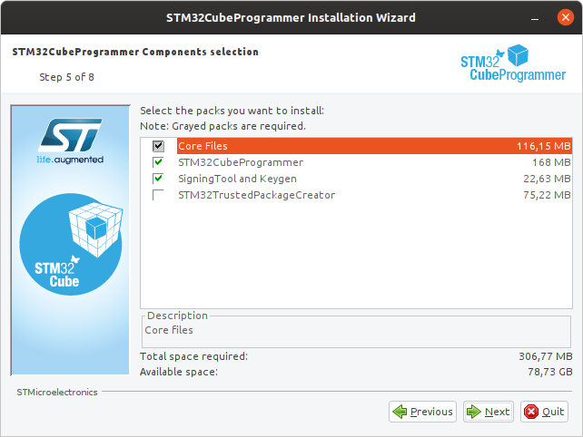
Install STM32CubeProg with default settings
Installation is straightforward. Proceed with the default options and allow installation of drivers on Windows. Do not modify installation path unless you don't want to do some extra configuration. If not found at the default path, the path of the programming utility must be added to PATH environment variable.
- Linux users have to install the drivers (copy USB udev rules). To do this, open a terminal in the subfolder which contains rules, copy them to system folder and reload udev rules. The next commands work with default installation path.
cd ~/STMicroelectronics/STM32Cube/STM32CubeProgrammer/Drivers/rules
sudo cp *.rules /etc/udev/rules.d
sudo udevadm control --reload-rules && udevadm trigger
For the next step, connect the ST-Link to PC. "Blue pill" boards usually have STM32F103C8 microcontrollers. In reality there are two versions around, with 64 kBytes and 128 kBytes of internal flash, with the same markings on the chip. It's important to know what flash size you have. You can do this from the GUI (just make sure ST-LINK is selected and click Connect):
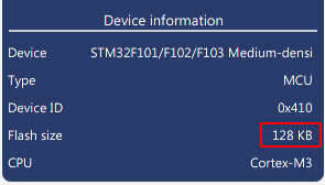
Check flash size in STM32CubeProgrammer
It can be done from command line too. You must launch the command line utility in the bin subfolder.
cd ~/STMicroelectronics/STM32Cube/STM32CubeProgrammer/bin
./STM32_Programmer_CLI --connect port=SWD
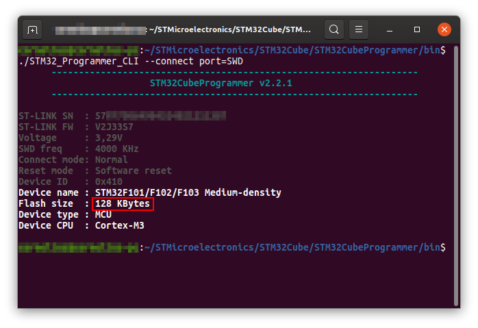
Check flash size in STM32CubeProgrammer (CLI)
I showed you Linux screenshots, yet the CLI programming utility can be launched in Windows Powershell too. Note that you will see the above info in Arduino IDE log when uploading sketch.
Arduino IDE
Launch Arduino IDE and go to File - Preferences. Add the following URL in the Boards Manager URLs:
https://github.com/stm32duino/BoardManagerFiles/raw/master/STM32/package_stm_index.json
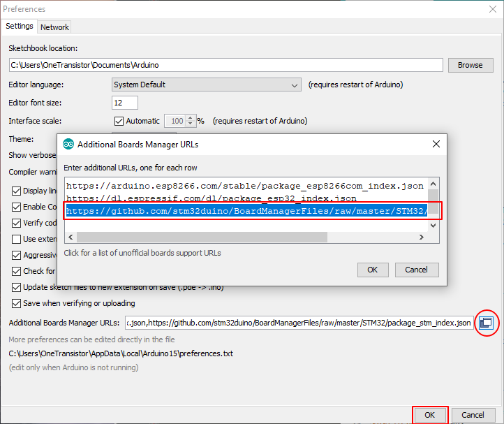
Arduino IDE - add Boards Manager URLs
Next, go to Tools - Boards - Boards Manager. In the dialog that appears, search for STM32 and choose STM32 Cores by STMicroelectronics. Click on Install and wait for it to download the required tools and libraries.
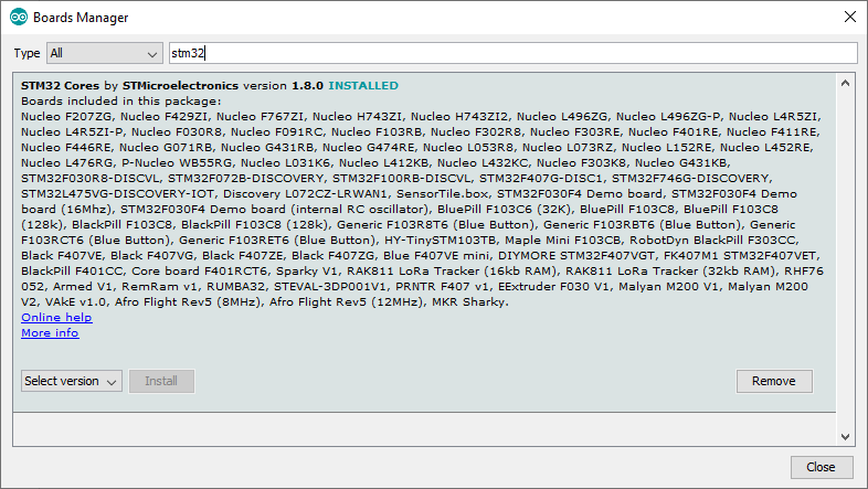
Arduino IDE, Boards Manager - install new board
You can see by now the huge list of supported development boards. After it finishes, select the following board with options:
- Board: "Generic STM32F1 Series"
- Board part number: "BluePill F103C8" or "BluePill F103C8 (128k)" (first option is for 64 kB flash)
- Upload method: "STM32CubeProgrammer (SWD)"
These are the required steps to be able to upload a sketch.
Sketch
Let's write something simple based on Blink and add some serial port output.
void setup() {
  Serial.begin(115200);
  while (!Serial) ;
  pinMode(PC13, OUTPUT);
  Serial.println("STM32 blink test");
}

void loop() {
  digitalWrite(PC13, HIGH);
  delay(1000);
  digitalWrite(PC13, LOW);
  delay(1000);
  Serial.print("Hello from STM32! ");
  Serial.println(millis() / 1000);
}
I regularly use the serial port for printing debug information and with Arduino boards things are simple. But "blue pill" has more than one serial port. The generic Serial instance can be used in two ways:
- Over the native USB port, "blue pill" is also powered from USB port, while the programmer is connected to a different USB port (power wire from programmer to board is not connected in this case). This method has a drawback. On every reset (which happens every time you upload a sketch) the USB port is reset too. The board's USB serial port gets disconnected from Arduino IDE Serial Monitor and you have to close and reopen Serial Monitor to open the port again.
- Over the USART1 pins (PA10=Rx, PA9=Tx), with USB-Serial converter (CH340G, FT232). Although it requires extra hardware, the port exists independently from the board and does not "disappear" when you reset "blue pill".
Therefore you have two options if you want to have a serial port that you can monitor and control from PC. Option 1 uses the native USB port of the board.

Board settings for USB Serial native port
Option 2 uses a serial interface connected to board's USART1. It's mostly useful if you're developing something that uses the USB port in a different way than serial emulation. In this case make sure you don't make the above selection of CDC (generic 'Serial' supersede U(S)ART). An USB hub can prove useful in such a situation.
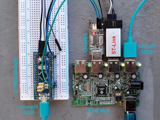
Bluepill programming with serial monitor over USART1 and USB interface
Next steps
Now that you got everything set up and running, go ahead and check the API differences/additions. STM32F103 is more complex than ATmega328. Since the Arduino support package is based on HAL and LL libraries, functions from these can be called from your sketch to make use of the advanced capabilities of the MCU. Take a look at the UM1850 manual.


Thanks for this, very helpful. I need some help. I want to do something very simple - I want to set up the clock chain for the fastest A to D and output the data on USB and do the programming on the Arduino IDE. All other data processing will be done in MATLAB. I feel like I need to become a system administrator to make this work. Any code snippets? Any ideas will be greatly appreciated.
ReplyDeleteI believe that the right way to do this is with HAL library from ST, not with Arduino SDK. Something like https://www.onetransistor.eu/2017/12/program-stm32-bluepill-hal-eclipse.html (note that post is a little outdated). Unfortunately I do not have experience with the ADC of STM32. You should also make use of the integrated DMA for your application.
DeleteWhile playing with the blink sketch provided, it turns out that it seems the digitalWrite(PC13, LOW) function turns on the led and the digitalWrite(PC13, HIGH) turns off the LED. Anyone else have this issue?
ReplyDeleteThis is normal behavior! The pin is active low because LED is wired to VCC.
DeleteNice Post
ReplyDelete