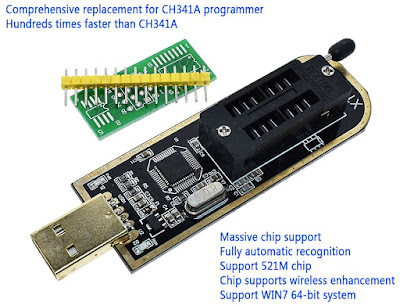
XTW100 is a new SPI/I2C memory programmer based on STM32 microcontroller. It is advertised as a comprehensive replacement for the CH341A.
I recently found a new serial programmer, the XTW100 Mini Programmer which is supposed to be an "upgraded" variant of the well-known CH341A Mini Programmer. Having a similar price to CH341A, I didn't wait any longer and ordered myself one. With a PCB slightly bigger (in length) than the PCB of CH341A, this new device is built around an STM32 ARM microcontroller. Having native USB port and hardware I2C and SPI, these microcontrollers with proper firmware could do a good job for this purpose.
Yet, there are some advertised features of this programmer that seem to good to be true (for a 4 USD programmer). Just as I did with the CH341A, I will try to draw the schematic and look for drivers and software for this XTW100 memory programmer. Because the STM32 is a 3.3 V device I can say for sure that this programmer will not have the 5 V bus levels issue. I got my XTW100 from AliExpress / WAVGAT store.

Product photo of XTW100 programmer
It is claimed that this programmer is able to switch supply voltage for the memory between 3.3 V and 5 V depending on the selected chip. Besides this, the software includes 1.8 V chips in its known devices list. We'll see whether this voltage switching is true or not. However, I'm still struggling to understand what they mean with "Chip supports wireless enhancement" ...
Hardware
The programmer is built around STM32F103C8T6 ARM 32-bit microcontroller. This and a linear voltage regulator (AMS1117-3.3) are the only integrated circuits on the PCB. I'm still wondering how they switch voltages. From the first look I can see this one does not have additional pin headers like CH341A has. Those connectors for serial port and SPI port proved useful for me and definitely make the programmer more versatile. Unfortunately, XTW100 does not feature similar ports.
Note that the same microcontroller is used by "blue pill" development boards. STM32F103C8 is a device with Cortex-M3 ARM CPU that runs at maximum 72 MHz, 20 kB of RAM and 64 kB of flash memory. The microcontroller (MCU) has USB port, two serial ports, 16-bit PWM pins and 12 bit ADC pins. It runs at 3.3V, but some of its pins are 5V tolerant.

Schematic of XTW100 MinProgrammer
With a multimeter and a couple of hours I was able to trace the schematic of this programmer. First of all, as I supposed, this is a 3.3 V device. SPI bus is wired to a hardware SPI port of the STM32 (SPI2 on pins PB12..PB15). That's a good thing. It means good overall transfer rates with the highest available SPI clock frequency on this MCU (18 MHz) - if configured by software.
With I2C they chose a totally different configuration. While I2C1 pins PB6 and PB7 are used to drive the LEDs, I2C2 pins PB10 and PB11 are used as GPIOs to provide ground connection for the SPI memory, there is no hardware port available for I2C. It must be implemented in software, but that's no big deal.
Strange way of powering the memory chips though. 3.3 V supply is coming from the voltage regulator which also powers the CPU, yet the ground is controlled by software. Two GPIO pins for each memory chip are pulled down to create the voltage that will power memory ICs. In this way the current through any chip you may plug in the programmer is limited to 2 x 25 mA/pin = 50 mA. This limitation is a bit dangerous. Draw more and you may destroy those pins of the GPIO or the entire port if you're "lucky".
Current limiting is good for in-circuit programming, where you could end up powering more than the memory chip. But it should have been designed in a different way, not relying on the microcontroller to power chips from GPIOs.
These being said, I can't figure how could they use different voltage levels. Keep in mind that many 5 V serial memory chips are also 3.3 V compatible, so this programmer could be very well used for them. But that's a totally different thing from "The programming voltage is automatically switched".
Driver
This programmer has been initially designed and manufactured by Zigong yaojie Electronic technology Co., Ltd. They also provide software and driver for download. Although the software package is last updated in 2019, the driver is not digitally signed and will not install seamlessly on Windows 10.
Fortunately, their driver is nothing more than a libwdi generated INF file which uses libusb. So, get Zadig and install libusb-win32 driver (important: only this one works with their programming software) for the WinUSBComm Device with the specific IDs 1FC8:300B. Proceed with caution in order not to replace the driver of another USB device.

Install libusb-win32 driver for XTW100
Follow-up
Is it worth switching from CH341A to XTW100? Well, it's a good addition to my toolbox, but I'm not sure it can replace CH341A Mini Programmer. In a follow-up post (I actually bricked its firmware) I'll actually use it (got a new one) and sample the buses with the oscilloscope.


Good Job! reversing engineering programmer unfortunate is already old and doesn't have software in English. Much better alternative is XTW-2 cheaper, faster and improved over this one.
ReplyDeletehttps://www.aliexpress.com/item/32988300257.html?spm=a2g0s.9042311.0.0.71f14c4d52Ynra
I found and used it myself a CH341A that has a multi voltage switch (1.8V, 2.5V, 3.3V 5V) but the price is a little higher:
ReplyDeletehttps://www.aliexpress.com/item/4001272558261.html