Build this relay countdown timer with LM3914 LED bargraph driver and LM358 opamp
LM3914 and LM3915 are dot/bar display drivers used to create basic displays of analog voltage levels. They are widely used in VU-meters and various voltage indicators (for batteries). The LM3914 senses an analog voltage and drives a number of LEDs depending on the level of this voltage. Knowing this, we can provide this voltage from a discharging capacitor. Depending on the resistive load which discharges the capacitor, the time required to turn off all LEDs can be set to specific intervals. This is how a timer is made using LM3914 (or LM3915).
This IC contains a constant current source for LEDs and an adjustable voltage reference. The following circuit uses LM3914 internal current source to charge the capacitor. To be able to modify countdown time, a potentiometer is used to discharge the capacitor. When the last LED is off two opamps drive a relay. The two opamps are part of the LM358 integrated circuit and one of them is used, in a similar manner, with a capacitor that is charged/discharged to provide an optional turn-off time for the relay. By setting a jumper you can choose between relay always on after time is up or relay on for an adjustable amount of time.

LM3914 countdown timer built on PCB
The circuit is powered from 12V DC and requires a total current of less than 100 mA. The countdown timer is started by pushing SW1. All LEDs will be on and after a while will begin to turn off starting from D14. The discharge curve of C1 is affected by RV1+R3 resistance. Although I used a 10 μF capacitor (C1), I recommend replacing it with a 100 μF or more for practical uses. With my 10 μF, the timer is off in less than 10 seconds. I also tested with 220 μF and I was able to get a countdown time between one and four minutes (by adjusting RV1). If you increase value of C1 you may also decrease resistance of R1.
Erratum: Both the schematic and the PCB design depict C1 misplaced. Its cathode (minus) should go to pin 5 of LM3914. Just remember to solder it the "wrong" way. RV1 and R3 should pull down the negative terminal, not the positive one. Improper functioning will certainly occur if this capacitor is not placed in circuit with correct polarity.

LM3914 countdown timer schematic
Q1 and Q2 are generic purpose NPN transistors which drive the relay. They are wired that way to make an "AND" gate, so that the relay is activated only when both opamp outputs are high. Let's see why this was needed. Well, when the timer is running and the last LED (D2) is still on, U2A output is low. This also means C3 is discharged via R9, therefore U2B output is high. The relay must be off and this happens because U2A is low.
When the last LED is off, the potential difference across it becomes very low (LM3914 pin 1 goes high). U2A output switches to high and it begins to charge C3 via R8+RV2. While C3 is not charged enough, U2B output remains high. This is the moment when the relay is activated by both opamps. When C3 is charged, U2B output goes low and disables the relay. If you don't like this behavior, you can use J2 jumper to short-circuit Q2 (which is driven by U2B). In this way, the relay will remain always on after the time has passed and the last LED is off.

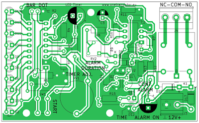
LM3914 timer PCB outline
I fitted everything on a 90 by 55 mm single layer PCB which can be made at home. Three wire jumpers are required as drawn on silkscreen. I found it hard to get a 1 megaohm trimpot for RV1 and I was lucky to find an old Piher PT-15, larger than potentiometers nowadays. I'm giving you the KiCad Project so that you can replace that footprint with what you have.
This circuit uses common parts. R5 can be 1.8 kilo-ohms (I used 2 kilo-ohms because I have a bunch of unused resistors of this value). I recommend bargraph mode which is selected by placing a jumper on pins 2-3 of J1 (note that a jumper is required on J1). An optional jumper may be placed on J2 1-2 to enable infinite relay activation after time has ended. LED D12 remains on to inform that the time has ended, while D15 signals the relay is activated.
Resources
- The LM3914 part of this circuit appeared in Romanian electronics magazine Conex Club, issue 77 from March 2006. See the PDF here, page 13. They reference this as a kit of AVT Poland. I added the LM358 and relay sections of the circuit.
- As usual, the KiCad project with generated Gerbers and Drill files, ready to send to your favorite PCB maker (note that those wire jumpers will be copper tracks on top layer).


Hello, one transistor, I ask permission to visualize your project in 3d, then I will post on my personal fecebook page ... Do you allow thank you
ReplyDeleteYes, I allow that, but I would like a link to this page.
Deleteready and thank you ... i will include the link on the video description or facebook page
Delete