Trigger an alarm when a door is opened or a window is broken using this analog microphone based volumetric sensor
The following device can detect sudden small air pressure changes in a room caused by opening a door or breaking a window. It is therefore useful to automate lights or as alarm. Although it uses as detector a common electret microphone, the circuit does not react to sound. Used as an alarm, it will not trigger while you are in the room, unlike infrared and ultrasound movement detectors which need to be deactivated when you are home.
I found this circuit in an old electronics magazine and I decided to build it without expecting too much from a microphone based air pressure sensor. The circuit is purely analog, without microcontrollers. Yet, as I found out it does its job very good. Microphone signal is filtered and amplified using common opamps and a couple of 555 timers keep the relay activated for an adjustable amount of time.

Built volumetric sensor
Let's take a look at the schematic to understand how this thing works. It is said that a pressure variation appears at the microphone output as a 0.7...4 Hz signal.

Microphone volumetric sensor schematic (click on image for full size)
Signal from microphone is amplified and low-pass filtered by U1B (LM324). The cut-off frequency is about 4 Hz. U1A opamp provides electret microphone supply of about 2.5 V. The filtered signal is further amplified 45 times by U1C. The last opamp in the LM324 capsule (U1D) keeps the 555 timers in reset mode for a while at startup. Therefore, the alarm is set when the yellow LED (ALARM) is on (at about 15 seconds after power-up).
Coming from LM324 U1C, the signal is fed to the LM358 based window comparator. At this stage the sensitivity can be adjusted with R17 trimmer potentiometer. Comparator output trigger the two 555 timers which have the following functions: U4 sets relay on time which can be adjusted with R24 trimpot and U5 adds a delay before triggering the relay. The choice to use this delay is made by setting a jumper on pins 2-3 of J1 header. Otherwise, with jumper on pins 1-2, the relay gets triggered instantly once an event is detected.

Volumetric sensor PCB
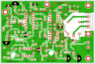
I redrew the schematic from the magazine in KiCad and redesigned the PCB (following their design though). The PCB for this circuit has a size of 98 x 66 mm and is double sided. Since I couldn't make it myself using toner transfer method, I ordered it from PCBWay. All parts are through hole devices.
If proper built, the circuit will work without any special adjustments. Power it up and wait for the ALARM LED to be on. Once this happens, the alarm is active. If you blow air into the microphone you can trick it to trigger the relay (the red LED RELAY will be on as long as the relay is triggered). Use R17 and R24 to adjust sensitivity and duration of relay activation, respectively.
Resources
- This circuit appeared in the May 2006 issue of Conex Club Magazine (page 31). No longer published, the archive of this Romanian electronics magazine can be found at http://www.conexclub.ro/ (direct link to May 2006 PDF issue).
- They reference French Magazine Electronique et Loisirs, no. 39, and claim this circuit was a kit sold by Comelec (EN1506).
- A version with less parts of this volumetric sensor can be found at Red Circuits (maybe this one was first published?).
- Download here the KiCad project: volumetric_sensor.zip (archive includes Gerber and Drill files and can be sent to PCB manufacturing services).


No comments :
Post a Comment
Please read the comments policy before publishing your comment.