Find out what is the difference between current sink and current source capable outputs of digital integrated circuits and microcontrollers
Current source and current sink are two commonly used terms that you will find in datasheets of microcontrollers and digital circuits. Even though most input pins of an IC nowadays are internally connected to the gate of MOSFET transistors which are voltage driven, there are situations when you have to take into account current capabilities (i.e. high speed switching or something else than a CMOS input is connected to an output pin). I'm thinking about LEDs and bipolar transistor driven devices, such as relay modules.
These inputs are current driven and need to source or sink currents to change state. Fortunately, most output pins of contemporary microcontrollers are push-pull type and can source and sink currents. This means you don't have to worry too much about the way you are connecting an LED to a digital output. But there are still in use circuits which can only sink or source currents. And if you're not paying attention to datasheet, you might very well fail to design a working circuit.
Sink versus source
Current source means the pin can supply current to a load. Although that current is low (a few mA) is usually enough for driving an LED or the base of another transistor. Internally, when you set a source capable pin to high, a transistor switches on and "ties" that pin to VCC. A bigger load which needs current above the specifications of the device, will damage the output transistor.
On the other hand, current sinking pins drive loads by drawing currents from them. If you wonder how can this be, the only condition that needs to be met is to create a potential difference in order to determine a current flow. Therefore, a current sinking pin has an output transistor which "ties" it to ground when activated. The load must be connected between this pin and VCC and the current will flow when the output transistor is activated.
Internally, output transistors of output pins will have a weak pull-up or pull-down resistor. Actually, this may not be a resistor, but a very low constant current source/sink. This allows a very small current (less than 1 mA) to be sourced from a sinking pin, or to be sunk from a sourcing pin. But there are output pins which can sink and source similar amounts of current. This is because nowadays microcontrollers use push-pull output configurations. Let's see how this works with some explanatory schematics.
 |
| Types of output pin configurations |
Current source
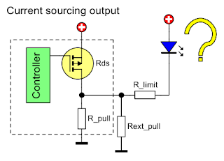
If the pin can supply current to a load, it's obvious you can connect a load to ground. This kind of output is active high.
 |
| Current sourcing output connection |
In the above example, assuming the P-channel MOSFET transistor is off, its drain-source resistance (Rds) is very high (a few giga-ohms). The current will flow through the blue LED, via the current limiting resistor (R_limit) and the internal pull-down resistor (R_pull) to ground. Since R_pull has a high resistance (and that's something you can't quite change), the blue LED may not light at all or it will be very dim.
When the transistor switches on, Rds goes low (less than 1 ohm). Current flows from VCC, through transistor D-S, then via R_limit it forward biases green LED and makes it light brightly. This time, the current amount flowing through LED is controllable by R_limit, and upper-limited by the capabilities of the transistor.
So, how can you make the blue LED light up (without changing the schematic)? There is a solution with a caveat. Add a parallel resistor to the internal pull-down (put your own pull-down resistor between output pin and ground).
 |
| Adding a pull-down to current source output |
Now, when the transistor is off, there is a higher and user selectable current flowing through the LED, with the help of Rext_pull. That is fine. The LED is on. But what happens when you want to turn it off? The transistor must source a high current through Rext_pull with the only purpose of keeping the output high. And that current must not exceed its limits. In other words, with a carefully chosen pull-down resistor you can achieve this, albeit increasing power requirements. This is actually a perfectly fine solution with inputs which require lower currents (transistors which need to be biased).
With this configuration, you made the output active low. And here comes the other potential issue. The initial state of the controller may cause problems. What I mean is that after power on, before the controller starts processing commands and setting the transistor, this is probably off. And your LED is on. This is completely undesirable in some situations. Take the example of a relay switching on a motor. You don't want it on for a fraction of second when you power-up the controller.
In other words, use current source outputs with ground connected loads.
As a side note, N-channel MOSFETs are preferred over P-channel ones in high power applications and are sometimes used to source current, with the load connected between source pin and ground. Although this increases the complexity of the driving circuitry (because gate voltage must be maintained higher than source voltage), it is commonly used to supply high amounts of current mostly because Rds(on) is lower for N-channel transistors, which results in less power losses across drain-source junction.
Current sink
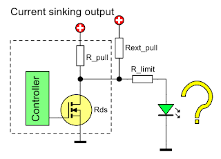
If the pin can draw current, you will connect the load to supply voltage. This kind of output is active low.
 |
| Current sinking output connection |
In the above example, assuming the N-channel MOSFET transistor is off, its drain-source resistance (Rds) is very high. The current will flow through the green LED, via the internal pull-down resistor (R_pull) and the current limiting resistor (R_limit). Since R_pull has a high resistance (and that's something you can't quite change), the green LED may not light at all or it will be very dim.
When the transistor switches on, Rds goes very low. Current flows from VCC, through blue LED and R_limit, then via transistor D-S to ground. The blue LED is now brightly on. The current amount flowing through LED is controllable by R_limit, and it upper limit is set by the capabilities of the transistor.
So, how can you make the green LED light up (without changing the schematic)? It the same way I shown above, with current source. This time, a pull-up is needed.
 |
| Adding a pull-up to current sink output |
The same issue will be encountered. By default, when transistor is off, the LED stays on. Rext_pull causes a high current flow only to keep the LED off (when transistor goes on).
In other words, use current sink outputs with supply connected loads.
Push-pull
This type of output configuration brings the best features, being able to both sink and source current. Instead of maintaining one of the states with a pull resistor, a second, complementary transistor is used.
 |
| Push-pull output connection |
There is not much to say here. When one of the transistors is switched on, the other goes off. In this way, in each state, the current flows through the load via one of the transistors. Loads may be connected either way (to ground or to supply voltage) since sink and source currents are usually equal.
Practical example
Enough theory, let's build something. Where can I find such a limited digital IC which can only sink or source current? Well, apparently the bus I/O expander PCF8574 can only sink current on its parallel output port. It doesn't say that on the first page of the datasheet? Yeah, I know, I found it the hard way (after building a PCB where it should drive ground connected LEDs). They even say "Latched Outputs With High-Current Drive Capability for Directly Driving LEDs". This was all I needed to throw away the datasheet and build my LED driver with this amazing IC. Only to find I missed something - and I am not the only one. I extracted the following from datasheet:
- Absolute maximum ratings:
- Continuous output low current (IOL): 50 mA;
- Continuous output high current (IOH): -4 mA;
- Recommended operating conditions:
- High-level output current (IOH): -1 mA;
- Low-level output current (IOL): 25 mA.
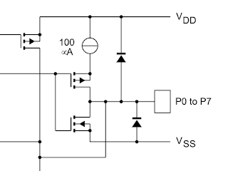
Note the convention to define sourced current as negative. The parallel port of PCF8574 can also be set to input and I'm assuming this is why they used this kind of output limitation. In fact the ports of PCF8574 are push-pull, however the source of the P-channel transistor is current limited (the current source in schematic below is 100 μA).
 |
| I/O ports of PCF8574 (extracted from datasheet) |
Let's connect a couple of LEDs to the outputs of this IC and see what happens. On a breadboard, I wired one LED to ground and the other to VCC and tried to drive both. For consistency, I used identical LEDs (5 mm red LED with a forward voltage drop of about 1.91 V - measured with my GM328A component tester).
 |
| LEDs driven by PCF8574. Top LED is properly connected, active low. Bottom LED needs current from the output pin because it is connected to ground. |
The results are clear. With a 330 ohms limiting resistor, the current through the properly connected LED is 8.5 mA, at a pin low voltage level of 117 mV (close to ground). The current through the other LED is only 162 μA at a pin high voltage level of 1.775 V (far from 5 V supply voltage)! This high efficiency LED still emits light, even it isn't properly forward biased.
#include <Adafruit_PCF8574.h>

Adafruit_PCF8574 pcf;

void setup() {
  pcf.begin(0x20, &Wire);
  pcf.pinMode(7, OUTPUT);
  pcf.digitalWrite(7, LOW);  // current sinking LED
  pcf.pinMode(2, OUTPUT);
  pcf.digitalWrite(2, HIGH);  // current sourcing LED
}

void loop() {
}
I used the above code to set PCF8574 pins to output, taking into account active low or active high state for each connection type. It requires Adafruit library for this IC.
Conclusion
Having a good knowledge of output pins current capabilities will help you avoid potential interfacing issues when interconnecting various peripherals with microcontrollers or other digital ICs. I think PCF8574 is a rare example of current sink only output pins in today's digital IC market.
The first question that comes to my mind is if it is really suitable for driving HD44780 LCDs? Well, as far as I can understand from the datasheet, all inputs are used to drive gate of MOS transistors. And, with the exception of E signal, all of them are pulled-up with a maximum current of 250 μA (page 51 of datasheet). Leakage current is less than 1 μA. Therefore PCF8574 can drive HD44780 while being used within datasheet specification.
In the next post we'll see what else can be driven by PCF8574.


You have mentioned in paragraph "Current Source":
ReplyDelete"In other words, use current source outputs with ground connected loads."
and then in paragraph "Current Source":
"In other words, use current source outputs with supply connected loads."
Isn't that confusing?
My mistake. Read the corrected comment as below
DeleteYou have mentioned in paragraph "Current Source":
"In other words, use current source outputs with ground connected loads."
and then in paragraph "Current Sink": (this was incorrect in first comment)
"In other words, use current source outputs with supply connected loads."
Isn't that confusing?
Yes, there was an error in text. I fixed it. Thank you!
Delete