Learn to use PCF8574 and 74HC595 to drive relay modules when your development board has a limited number of available pins
In automation projects it is often needed to drive multiple outputs. Combine this with the reduced number of pins of a microcontroller, such as ESP8266, and you got a problem. In this post we'll explore the methods of converting the parallel inputs of a relay module to some kind of serial protocol, which allows connecting even more relays, without the need of additional control pins. I will use for exemplification an 8-channel relay module, however the methods I will show will allow you to connect more than 8 relays to the same bus.
To achieve this purpose, I have to use some kind of bus expander IC. There are a few available options here. However, as we will see, both communication protocol and output port capability are different. And even the common relay modules use a rather unusual method of turning on the relay driver transistor. I already discussed the difference between current sink and current source in the previous post. Let's use that knowledge.
 |
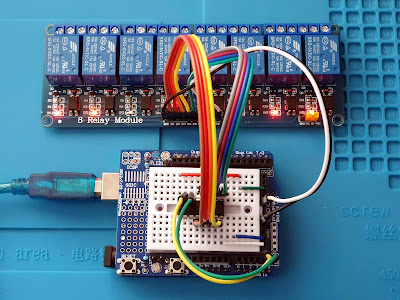
| 8 Relay module with PCF8574 bus expander |
The relay module
I'll start with this, because in order to drive it I must understand how does it work. When you buy such modules, their specifications should let you know the driving voltage levels. However, as they come with absolutely no documentation, let's analyze the schematic of a common relay module, and some less common ones. This is how one driver of the module from above photo looks:
 |
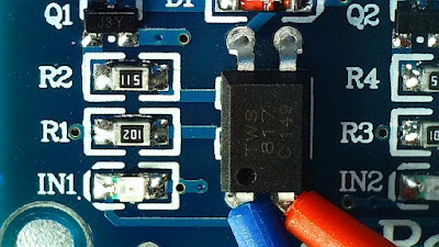
| Relay driver with optocoupler |
R1 pulls up optocoupler TWS817 C 149 and the series LED IN1. Input signal is applied at the cathode of this LED. Optocoupler drives the base of Q1 which is S8050 (J3Y marking), which turns on and connects relay coil to ground. In the above photo you can see my test leads on the optocoupler LED pins to measure its forward voltage. I assume TWS817 is equivalent to PC817. According to datasheet, its input forward voltage is typically 1.2 V, with a maximum of 1.4 V. Forward current should not exceed 50 mA.
I measured optocoupler forward voltage and it is 1.18 V, very close to datasheet. I also measured IN1 LED forward voltage, because I cannot find its part number to search for a datasheet, and I got 1.96 V. When both are measured in series, the voltage drop is 3.07 V (less than the sum of both taken separately). Let's draw the schematic and analyze it.
 |
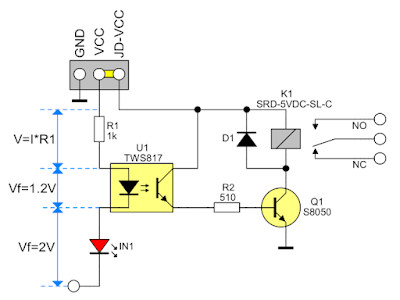
| Schematic of a single relay driver |
Let's take it from right to left (parameters of each component are from datasheets). The relay coil requires 71.4 mA which is way less than the maximum collector current of S8050 (0.5 A). There are no additional markings on the transistor case, so I will assume the lowest gain of 120. The base must be sourced with at least 71 mA / 120 = 0.6 mA. Providing 10 times the minimum base current (6 mA) will certainly saturate the transistor. Therefore the optocoupler must source at least 6 mA to the base of Q1 via R2.
This is certainly possible with R2 of 510 ohms and 5 V supply (assume 0.8 V drop across Q1 base-emitter and 1 V drop across collector-emitter of optocoupler - which is rather high - but even so, the current is 5 - 0.8 - 1 = 3.2 V divided by 510 ohms = 6.2 mA). One last look into the datasheet of PC817 shows that with only 1.5 mA input forward current, I can get 600 % transfer ratio (therefore a collector current of 9 mA, more than the required 6 mA).
I finally got the the input characteristics of this relay driver. In order to activate the relay, a digital output pin must sink at least 1.5 mA. Assuming 5 V supply voltage, when input pin is pulled low. R1 resistor limits current flow to (5 - 3) / 1000 = 2 mA. Just enough! For convenience, the relay module designer added a jumper which allows using different power sources for relays and optocoupler.
Does that mean I can power optocouplers from 3.3 V (VCC) and relays from 5 V (JD-VCC)? Because of the series LED this is not possible. Given its high characteristic voltage drop, a 3.3 V supply cannot guarantee enough current flow with the existing limiting resistor R1 of 1 k. But that doesn't mean I cannot use 3.3 V digital outputs to drive this module. Relays are activated when pin is set to low. When high, the potential difference across R1-U1-IN1 is only 5 - 3.3 = 1.7 V, not enough to determine a current flow, so the relay will certainly stay off.
In conclusion, this type of relay module features a simple yet smart design and can be driven by 3.3 V and 5 V digital output pins, which are able to sink at least 1.5 mA. Outputs are active low. Retailers could have bothered to mention these specs.
 |
| Other possible relay driver configurations |
There is also a different relay module manufactured by Keyestudio. I do not own this and I cannot make any assumptions, but from the photos it seems to have a different driver. And it is specified the relays are activated by high signal. The placement of LED between driver transistor and relay makes me believe the transistor also turns on the LED. In this situation the driving signal must forward bias only the optocoupler (see the middle schematic in the above illustration). If you got a module without documentation, take a closer look at the PCB before using it.
I2C with PCF8574
PCF8574 is a parallel 8-bit bus extender with I/O capabilities and I2C interface. When being used in output mode, only the two I2C wires are required to interface with microcontroller (MCU). When set to input, an additional interrupt signal may be required to inform MCU when input data changes. With 3-bit configurable addresses, you can use up to 8 controllers to drive 8 relay modules, giving a total of 64 relays driven over two wire I2C.
PCF8574 can drive loads up to 25 mA (the absolute maximum being 50 mA), but there is a catch. Its output pins can only sink current! Those pins are very limited when required to source current, being limited to no more than 1 mA.
Therefore, PCF8574 is a perfect choice to control an 8-channel relay module as long as you get the one with active low drivers. It can be powered from 3.3 V or 5 V. At power on, the I/Os are high. In this mode, only a current source to VCC is active. This is a good thing and it means our relays will stay off before the MCU sends I2C commands to configure output port.
In fact, when you set a pin to high, it is actually weakly pulled-up and suitable to be used as input. Therefore, writing 0x00 to the parallel port of PCF8574 will turn on all relays. Writing 0xFF will turn off all of them.
#include <Wire.h>

void setup() {
  Wire.begin();
}

void loop() {
  // turn on all relays
  Wire.beginTransmission(0x20);
  Wire.write(0b00000000);
  Wire.endTransmission();

  delay(1000);

  // turn off first four relays
  Wire.beginTransmission(0x20);
  Wire.write(0b00001111);
  Wire.endTransmission();

  delay(1000);

  // turn off remaining four relays
  Wire.beginTransmission(0x20);
  Wire.write(0b11111111);
  Wire.endTransmission();

  delay(1000);
}
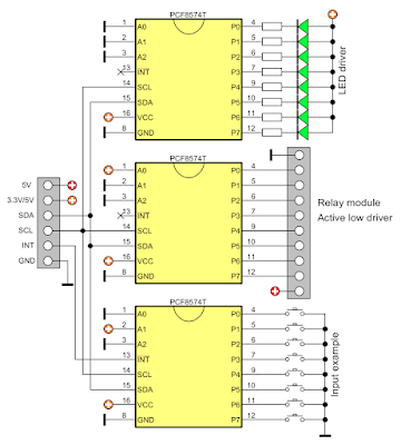
That's all the code you need. Libraries do exist, but I do not understand why you would need a library for such a simple data transfer (yeah, I know I used one myself at the end of this post). The address of PCF8574 is 0x20 when all three address pins are shorted to ground. Do not leave them floating as I did on the breadboard. After you wrote 0xFF to PCF8574, you can read port state by requesting a byte over I2C (that is if you want to read a keypad, for example). It is that simple (see the schematic below of a LED, relay module and keypad controller).
 |
| Example of a PCF8574 driver for LEDs, relay module and keypad |
Note the address pins in the schematic above. The top PCF8574 has all off them wired to ground (A[2:0] = 0, address 0x20), the middle one has A0 connected to supply voltage (A[2:0] = 1, address 0x21), while the one at the bottom has A1 connected to supply voltage (A[2:0] = 2, address 0x22). To read the keypad, make sure you don't write 0x00 to PCF8574 (if you do so, send a 0xFF to set it back to input), then request one byte.
An alternative with more features is MCP23008 which offers similar sink/source currents and additional port configuration registers. It is however more expensive than PCF8574 and it is harder to program, requiring 10 configuration registers to be set before writing or reading port register.
SPI with 74HC595
74HC595 is a shift register IC with 8-bit tristate output port controlled over a serial SPI-like protocol. Although it requires more data pins, it has the advantage of theoretically unlimited number of chained 74HC595s. You can also add input ports with a different IC (see this post on shift registers).
 |
| Relay module driven by 74HC595 shift register |
The absolute maximum current sourced or sunk from a pin is 35 mA. It can control active low drivers as well as active high ones. It can be powered from 3.3 V or 5 V. At power on, the outputs have random states, therefore you must use an additional output enable signal after you sent data to parallel port.
Here is the code to get the same output as above (no library needed):
#define PIN_ENABLE 9 // active low
#define PIN_DATA 11
#define PIN_CLOCK 12
#define PIN_LATCH 8 // active low

void setup() {
  pinMode(PIN_ENABLE, OUTPUT);
  pinMode(PIN_DATA, OUTPUT);
  pinMode(PIN_CLOCK, OUTPUT);
  pinMode(PIN_LATCH, OUTPUT);

  digitalWrite(PIN_LATCH, HIGH);
  digitalWrite(PIN_ENABLE, LOW); // enable output
}

void loop() {

  // turn on all relays by setting 0x00
  digitalWrite(PIN_LATCH, LOW);
  shiftOut(PIN_DATA, PIN_CLOCK, MSBFIRST, 0b00000000);
  digitalWrite(PIN_LATCH, HIGH);

  delay(1000);

  // turn off first four relays
  digitalWrite(PIN_LATCH, LOW);
  shiftOut(PIN_DATA, PIN_CLOCK, MSBFIRST, 0b00001111);
  digitalWrite(PIN_LATCH, HIGH);

  delay(1000);

  // turn off remaining relays
  digitalWrite(PIN_LATCH, LOW);
  shiftOut(PIN_DATA, PIN_CLOCK, MSBFIRST, 0b11111111);
  digitalWrite(PIN_LATCH, HIGH);

  delay(1000);
}
74HC595 can only be used to output parallel data. However there is also 74HC165 which is the input only parallel shift register. Both can be daisy chained and both can share the same clock. No matter how many shift registers you add, the data line only goes to first of them. This is a long subject which I will discuss in a different post.
 |
| Example of 74HC595 driving LEDs and relay module |
There is much more versatility of this method. Starting with the most obvious, LEDs may be connected as you want. It can drive both active low and active high relay modules.
The relay module I'm showing can be controlled by a 3.3V powered 74HC595. However, this may not be true with active high modules, some requiring higher voltages to stay firmly on. In such situations a 3.3 V output bus from a microcontroller can be interfaced to 5V powered 74HCT595 ("T" stands for TTL levels compatible) which drives the module.
There is much more to say on this subject. Regarding the software part, with daisy chained shift registers, just add another shiftOut to send data to the next one.
Overview
Knowing when and how to use a bus expander will definitely help you in your projects. Such ICs are not limited to relay modules and can be used as well to drive LEDs, read keypads and communicate with older parallel data ports. For the relay module shown in this post, I would recommend PCF8574, since it is easier to use. Also, for keypads you design, I would recommend PCF8574 to read buttons.


No comments :
Post a Comment
Please read the comments policy before publishing your comment.