Program Raspberry Pi Pico with CircuitPython to emulate USB HID consumer control
A while ago I used STM32 bluepill board to emulate a consumer control device that would allow me to control volume and media playing on PC, over USB. Implementation wasn't very easy, since I had to modify an existing library to add support for consumer control HID class. Nevertheless, I succeeded and the details and my library can be found in this post.
Meanwhile, a new cheap development board appeared. It is the Raspberry Pi Pico which has native USB port. I thought this could be used as well to emulate a keyboard, mouse or consumer control HID. This board can be programmed in C/C++ or MicroPython. Since I wasn't willing to install the C/C++ development kit, I attempted to use MicroPython. Unfortunately, it lacks required modules for USB HID and rotary encoder. Then I found about CircuitPython, which is based on MicroPython and is supported by Adafruit. At its current version, it is bundled with rotary encoder module and, for USB HID, you can use Adafruit HID library.

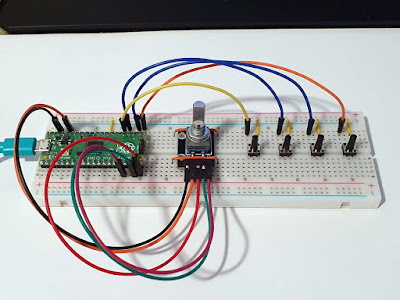
Media control device built on breadboard
Setting up and coding on CircuitPython is fast and straightforward. If you have previously used the Raspberry Pi Pico, it is probably running MicroPython. I'll show you how to install CircuitPython, how to connect rotary encoder and buttons and, finally, the full code for emulating the HID consumer control device.
Install CircuitPython
Hold down BOOTSEL button on your Raspberry Pi Pico and plug it into the USB port. Download CircuitPython UF2 file and copy it to RPI-RP2 storage device (which appears when you plug Raspberry Pi Pico holding down the button).
The board will restart and a new storage drive will appear. This time it is labeled CIRCUITPY and it has the correct capacity of less than 1 MB. Here, Python scripts and libraries will be stored.
Wiring
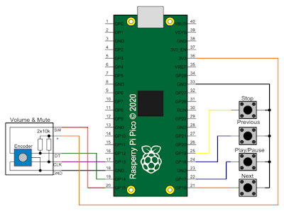
Rotary encoder and push-buttons can be connected to any general-purpose digital pins. Below is my wiring. The encoder is actually a module from a kit and comes with pull-up resistors on encoder outputs. It doesn't have a pull-up resistor on encoder button, which is wired to ground. So are my buttons, wired to ground, without pull-ups. RP2040 MCU of Raspberry Pi Pico can apply pull-ups as you will see in the code section.

Raspbery Pi Pico media buttons schematic
Library and code
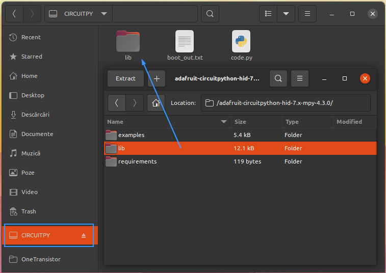
To run the Python code, Adafruit CircuitPython HID library is needed. You should always get the latest -mpy version, which is a compressed version of the library (i.e., at the time of writing this, adafruit-circuitpython-hid-7.x-mpy-4.3.0.zip). Extract the archive and you will find a lib folder. Copy this folder to CIRCUITPY storage.

Install Adafruit library to Raspberry Pi Pico
As you probably see in the screenshot, the code that will follow is in the file named code.py on the Raspberry Pi Pico storage. In less than 100 lines of Python code, I had all the functionality I wanted.
import time
import digitalio
import board
import rotaryio
import usb_hid
from adafruit_hid.consumer_control import ConsumerControl
from adafruit_hid.consumer_control_code import ConsumerControlCode

# Rotary encoder
enc = rotaryio.IncrementalEncoder(board.GP13, board.GP14)
encSw = digitalio.DigitalInOut(board.GP15)
encSw.direction = digitalio.Direction.INPUT
encSw.pull = digitalio.Pull.UP
lastPosition = 0

# Media buttons
btnStop = digitalio.DigitalInOut(board.GP19)
btnStop.direction = digitalio.Direction.INPUT
btnStop.pull = digitalio.Pull.UP

btnPrev = digitalio.DigitalInOut(board.GP18)
btnPrev.direction = digitalio.Direction.INPUT
btnPrev.pull = digitalio.Pull.UP

btnPlay = digitalio.DigitalInOut(board.GP17)
btnPlay.direction = digitalio.Direction.INPUT
btnPlay.pull = digitalio.Pull.UP

btnNext = digitalio.DigitalInOut(board.GP16)
btnNext.direction = digitalio.Direction.INPUT
btnNext.pull = digitalio.Pull.UP

# builtin LED
led = digitalio.DigitalInOut(board.GP25)
led.direction = digitalio.Direction.OUTPUT

# USB device
consumer = ConsumerControl(usb_hid.devices)

# button delay
dl = 0.2

# loop
while True:
    # poll encoder position
    position = enc.position
    if position != lastPosition:
        led.value = True
        if lastPosition < position:
            consumer.send(ConsumerControlCode.VOLUME_INCREMENT)
        else:
            consumer.send(ConsumerControlCode.VOLUME_DECREMENT)
        lastPosition = position
        led.value = False

    # poll encoder button
    if encSw.value == 0:
        consumer.send(ConsumerControlCode.MUTE)
        led.value = True
        time.sleep(dl)
        led.value = False

    # poll media buttons
    if btnStop.value == 0:
        consumer.send(ConsumerControlCode.STOP)
        led.value = True
        time.sleep(dl)
        led.value = False

    if btnPrev.value == 0:
        consumer.send(ConsumerControlCode.SCAN_PREVIOUS_TRACK)
        led.value = True
        time.sleep(dl)
        led.value = False

    if btnPlay.value == 0:
        consumer.send(ConsumerControlCode.PLAY_PAUSE)
        led.value = True
        time.sleep(dl)
        led.value = False

    if btnNext.value == 0:
        consumer.send(ConsumerControlCode.SCAN_NEXT_TRACK)
        led.value = True
        time.sleep(dl)
        led.value = False

    time.sleep(0.1)
At the beginning, required libraries are imported. Rotary encoder is declared, then media buttons with corresponding pins. Built-in LED is used as feedback and lights for a short time when you push a button or rotate the encoder. In a while endless loop, encoder position and button presses are polled. Since all buttons are wired to ground and their corresponding pins are pulled up, when pressed, pin read should be 0.
You can use Thonny IDE to edit the code and run it on Raspberry Pi Pico. But, to run every time you plug the board into USB, it must be saved on CIRCUITPY device and named code.py.
Resources
My code is inspired from the videos of Don Hui from Novaspirit Tech (Raspberry Pi Pico - USB HID Auto Clicker with Circuit Python, Raspberry Pi Pico - DIY Macro Keyboard). Previous versions of CircuitPython did not include required rotaryio module, but starting with 6.2.0 it does.
Anyway, you can download an archive with all the assets I used (CircuitPython 6.2.0 UF2, Adafruit HID library 4.3.0 and my code). UF2 file must be copied to Raspberry Pi Pico in boot mode, while the contents of CIRCUITPY folder should be copied to CIRCUITPY device.


This is great! Exactly what I was looking for! I'll give it a go.
ReplyDeleteexcellent, made this too, very good tutorial!
ReplyDeleteGreat, got me started. Thank you
ReplyDeleteWill this work on other raspberry pi models as well?
ReplyDeleteThis only works on RP2040 based development boards.
DeleteGreat it works. But I have one weird behaviour: when I turn my encoder to the left/right I need to turn it twice before it changes volume. So, for example, I turn it clockwise I don't get volume up, I turn it once more, volume goes up. (Same for counter-clockwise or volume down)
ReplyDeleteHad the same issue. It seems to be caused by rotaryio module.
Delete