Control multiple I/O lines for a front panel using 74HC595 and 74HC165 shift registers with Arduino
This project started from a common issue I faced while trying to interface a relay board with a microcontroller: not enough I/O pins. My purpose is to control 8 outdoor lights; therefore, I got an 8-channel relay board, powered from 5 V. But I want to add some extra functionality: this controller should have a front panel with 8 push buttons and 8 LEDs. It should also take input from sensors with digital output. So, I got 16 inputs and 16 outputs to control.
The most available solution was to use shift registers, 74HC595 for outputs and 74HC165 for inputs. Initially I thought I could use an ESP8266 microcontroller, since it would allow me to add MQTT functionality. But I had no success with this: ESP8266 is a 3.3 V microcontroller, relay board needs 5 V levels, and although shift registers can operate properly with voltages as low as 2 V, they will not recognize as high (“1”) a voltage of 3.3 V (from ESP8266) when powered with 5 V. The reason I powered them with 5 V is because relays will not be activated by 3.3 V.
 |
| Front panel fitted on the plastic cover of a wiring box |
I had to change the project and decided to use two units. There is the outdoor unit, which will be controlled by Arduino Pro Mini. Front panel and relay board are directly connected to it, all powered at 5 V. I will use MAX485 transceivers to communicate with the indoor unit. This will be built around ESP8266, which will have MQTT capabilities. I might even add a display to this unit. The advantage of this is that ESP8266 gets better Wi-Fi signal. And I can control lights remotely even when MQTT or Wi-Fi are down. The disadvantage is that I must use a cable to interconnect units (RS485 requires 2 wires, plus another two to power indoor unit gives a total of 4 wires – I can find 4-wire cable in hardware stores, sold under the name of “alarm cable”).
Since my project is a work in progress, this post will describe the outdoor unit front panel, with 8 push buttons and 8 LEDs which are independently controllable.
Electronics
As I said earlier, the electronics is based on a 74HC595 which controls the LEDs and a 74HC165 which reads buttons. The serial clock is common to both shift registers. Besides serial data input and output, two more control signals are required: latch for output shift register and load for input shift register. A total of 5 control signals makes it possible to interface this panel directly to ESP8266.
 |
| Schematic of front panel |
The schematic is simple. I added some additional control signals which are disabled by default. On power-up the LEDs will light randomly until microcontroller resets their state. This is not an issue. Even so, by setting the solder jumper CE_SET to 2-3 you get access to output enable signal of 74HC595, and you can keep LED outputs disabled until MCU is ready. There are two more jumpers to clear 74HC595 register and to disable 74HC165. If you have additional MCU pins, you can take control of this signals. I’m saying this because the front panel can be used in any kind of projects.
 |
| Front panel PCB |
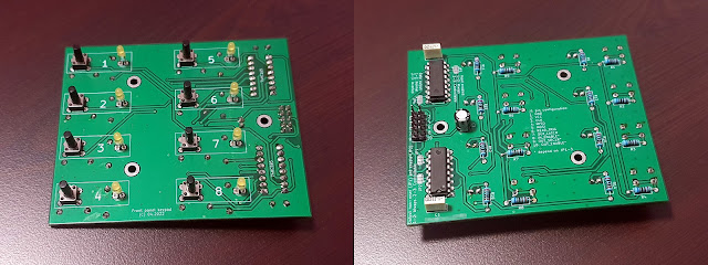
The PCB for this panel is 2-layer 95 x 80 mm. I used only through hole parts so I can assemble everything at home. However, the PCB must be professionally manufactured, since it has two layers, and you can’t make it at home. Only push buttons and LEDs are placed on top face. Everything else goes on the bottom face. Push buttons are G95 6 x 6 x 12 mm type (with long handle). Pull-up resistors R1 to R8 are 10 k each. LED current limiting resistors R9 to R16 are 330…470 ohms (according to datasheet 74HC595 can deliver up to 6 mA per output).
Software
In the final setup, there will be 16 inputs and 16 outputs, each with two daisy-chained shift registers. The following is a test sketch which controls only the shift registers available on front panel. I connected the front panel to SPI bus pins as follows (you can use any pins you want, the protocol is bit-banged):
In the sketch, at every 100 ms, the function which reads shift registers is called. The function is this:
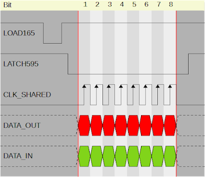
This code produces the following bitstream: load pin of 74HC165 is pulsed low to read current state of buttons; then latch of 74HC595 is switched low to signal incoming register data. In a single loop, data is exchanged for both input and output shift registers. At the end, latch of 74HC595 is reset to high.
 |
| The 5-lines serial protocol used by shift registers |
The example you can download from the link at the end of this post turns on and off the LEDs using their corresponding button in about 70 lines of code.
Enclosure
My front panel needed a proper enclosure. Therefore I designed one I could 3D print. There are two pieces. First piece holds the buttons. As you can see it uses two colors. I achieved this by pausing the print and changing filament.
There are 3D printers which support M600 command to change filament during printing. Unfortunately, my Artillery Genius Pro ignores this command, so I had to keep an eye on it while printing this piece. As soon as it got to the digits (which are 0.6 mm tall - 3 layers of 0.2 mm) I paused the print and changed filament. The end result looks great.
 |
| Front panel buttons piece |
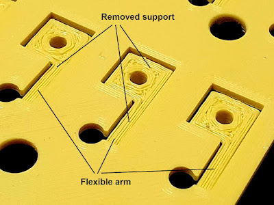
Note that both this and the face must be printed with supports. The buttons on this one are "floating" and the support beneath them needs to be carefully removed not to break the flexible arm holding the button. I could have designed this in a different way, because removing that support material required me to clamp each of the two columns of buttons in a vise and use a cutter and a screwdriver to get it out without breaking the button.
 |
| Back side of the button piece |
There is not much to say about the front face which I printed in blue. It requires supports. I used PLA for both pieces and 0.2 mm layer height, sliced with Cura.
Resources
- KiCad project with Gerber files: switch_panel.zip.
- Example code for this panel: switchbox_outdoor_frontpanel.zip.
- Models for 3D printing are available on Thingiverse: 5530365.
- Follow-up post: 8-Channel relay controller with keypad and RS485 interface.


No comments :
Post a Comment
Please read the comments policy before publishing your comment.