Showing posts with label 74HC595. Show all posts

Daisy chaining and bus sharing with shift registers

 Posted by:   Posted on:    1 comment

A shift register is a digital circuit that is used to store and manipulate data in a sequential manner. It is composed of a series of flip-flops, which can be viewed as basic memory units able to store binary values. The outputs of each flip-flop are connected to the inputs of the next flip-flop in the sequence, such that the data is shifted from one flip-flop to the next with each clock pulse.

In this post I will use the 74HC595 serial-in-parallel-out shift register and its counterpart, 74HC165 parallel-in-serial-out shift register. Both are commonly employed when a microcontroller with limited available I/O pins has to control a large number of digital outputs or read a similar number of inputs (for example in home automation). What I want to show you in this post is how to daisy chain these ICs and how to make them share some control lines in order to keep the serial interface data lines to a minimum.
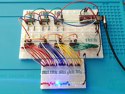
Shift registers circuit on breadboard

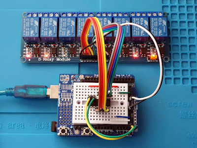
Drive 8-Channel Relay Module with Bus Expander

 Posted by:   Posted on:    No comments

In automation projects it is often needed to drive multiple outputs. Combine this with the reduced number of pins of a microcontroller, such as ESP8266, and you got a problem. In this post we'll explore the methods of converting the parallel inputs of a relay module to some kind of serial protocol, which allows connecting even more relays, without the need of additional control pins. I will use for exemplification an 8-channel relay module, however the methods I will show will allow you to connect more than 8 relays to the same bus.

To achieve this purpose, I have to use some kind of bus expander IC. There are a few available options here. However, as we will see, both communication protocol and output port capability are different. And even the common relay modules use a rather unusual method of turning on the relay driver transistor. I already discussed the difference between current sink and current source in the previous post. Let's use that knowledge.

8 Relay module with PCF8574 bus expander

8-Channel relay controller with keypad and RS485 interface

 Posted by:   Posted on:    No comments

In the previous post I built a front panel with 8 push buttons which will be used to activate a module of 8 relays. Having so many I/O lines I had to come with a solution to be able to read and set each one of them with common microcontrollers. I ended up using 74HC165 for inputs and 74HC595 for outputs. These ICs are shift registers controlled using a serial synchronous protocol similar to SPI.

In this post you will see the entire outdoor unit. In the end there will be two units, the outdoor one with keypad and relays; the other is the indoor unit with Wi-Fi connectivity and MQTT capabilities. A keypad will be featured on this one too. I went with this approach because I want a robust implementation without Wi-Fi dependency. Nevertheless the keypad on outdoor unit can be remotely disabled to prevent unauthorized use. I decided to use two units after a failed design which implied the use of an ESP8266 board directly as the MCU of outdoor unit. I had problems with voltage levels (shift registers are both 3.3 V and 5 V compatible, however my relay board is 5 V only, while ESP8266 is 3.3 V only; besides that, 3.3 V applied to shift registers powered from 5 V is not recognized as digital HIGH).

Relay controller inside plastic box

Front panel for 8-channel relay controller

 Posted by:   Posted on:    No comments

This project started from a common issue I faced while trying to interface a relay board with a microcontroller: not enough I/O pins. My purpose is to control 8 outdoor lights; therefore, I got an 8-channel relay board, powered from 5 V. But I want to add some extra functionality: this controller should have a front panel with 8 push buttons and 8 LEDs. It should also take input from sensors with digital output. So, I got 16 inputs and 16 outputs to control.

The most available solution was to use shift registers, 74HC595 for outputs and 74HC165 for inputs. Initially I thought I could use an ESP8266 microcontroller, since it would allow me to add MQTT functionality. But I had no success with this: ESP8266 is a 3.3 V microcontroller, relay board needs 5 V levels, and although shift registers can operate properly with voltages as low as 2 V, they will not recognize as high (“1”) a voltage of 3.3 V (from ESP8266) when powered with 5 V. The reason I powered them with 5 V is because relays will not be activated by 3.3 V.

Front panel fitted on the plastic cover of a wiring box