Showing posts with label Arduino. Show all posts

Receive weather station data with Arduino

 Posted by:   Posted on:    6 comments

A while ago (to be more specific two years ago) I used software defined radio to capture and decode RF signal from the outdoor unit of a weather station. This allowed me to emulate the protocol with an Arduino and a cheap 433.92 MHz transmitter and send my own data to the indoor station. I can make my own units if the original outdoor unit fails. The outdoor unit uses on-off-keying (OOK) and sends pulse distance modulated bits, explained in detail in the linked post.

But what about receiving data from outdoor unit(s) with an Arduino? One can add an ESP8266 to capture temperature and humidity and publish data to MQTT, Home Assistant or other IoT servers. Capturing and analyzing pulse timings of a signal was a daunting task for me. However it turned out to be easier than I thought, using an interrupt routine. In this post, I'll explain all the steps required to make a pulse distance modulation (PDM) decoder.

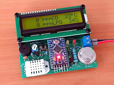
CO and LPG gas sensor with Arduino and LCD

 Posted by:   Posted on:    4 comments

In a previous post I looked at a MQ-9 sensor module. Unfortunately, although the sensor can detect CO and LPG, it cannot be used as it is wired in the module. After analyzing the datasheet I figured the best thing to do is remove it from existing PCB and build my own. In short, like other sensors from MQ family, MQ-9 has a heater resistor inside. In order to get any useful reading from it, this resistor must be heated at 5 V for 60 seconds, then cooled at 1.4 V for 90 seconds. The same is true for MQ-7. The issue with modules is that all sensors from MQ family are fitted on the same PCB design.

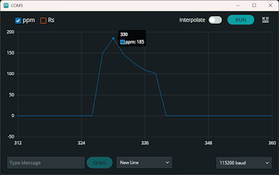
In this post, I'll share two other methods of powering the heater resistor and I will design a PCB. Sensor readings will be displayed on an alphanumeric LCD powered by Arduino. Since real ppm is temperature and humidity dependent, I will provide a PCB header for DHT sensor. I already tested the sensor with the LM317 power supply I built in the previous post, and I did some measurements.

CO and LPG gas sensor with Arduino and LCD

Influence of temperature and humidity on MQ gas sensors

 Posted by:   Posted on:    1 comment

I dedicated some of my previous posts to MQ gas sensors. These devices are cheap and can be bought on PCB modules, which implement a simple comparator circuit in order to provide a digital output. However, the usability of these modules is rather limited, knowing that some of the sensors from MQ family require variable heater voltage. More than this, at power-up the resistance of the sensor is low until the heater reaches working temperature, therefore the comparator output of a sensor module will trigger a false alarm.

Although this is not an important limitation, the modules do not take into account the variation of sensor resistance based on environment temperature and humidity. To do this, a microcontroller must sample the sensor resistance through an ADC and estimate gas concentration. This post continues a previous one in which I estimated gas ppm after extracting sensitivity data from datasheet graphs. However...

Influence of temperature and humidity on MQ gas sensors

Compute ppm of MQ sensors from datasheet graphs

 Posted by:   Posted on:    No comments

I tried to connect some of the gas sensor modules I have bought over time to Arduino. Unfortunately, I discovered these modules were not designed properly and require some modifications in order to power sensors according to datasheet specifications. I am using an MQ-2 type sensor for this test and all of the following estimations will be specific for this type of sensor. You can use the same approach to read and process analog input of any of the other sensors from MQ family.

You won't find in any of the available datasheets a direct, clear formula to approximate ppm of a gas based on the sensor resistance. But there are some sensitivity graphs which we can use to find a correlation. To make things even more complicated, for MQ-2 there are two datasheets available, from different manufacturers, with different sensitivity data.

Compute ppm of MQ sensors from datasheet graphs

Attempts at reading data from MQ-2 gas sensor

 Posted by:   Posted on:    No comments

MQ-2 is a gas leakage detecting sensor with good sensitivity to a wide range of gases. Since you can get most MQ sensor on ready-made modules, people are interfacing those with development boards. However, the modules are far from perfect. Some of the sensors require variable heater voltages. This is not the case for MQ-2. Since I own a module with this sensor and it can probably be used as is, I decided to make some tests while I'm waiting a PCB for MQ-9 to be manufactured and shipped.

In the previous post I explained why modules with MQ-7 and MQ-9 are no good. Now, I'm about to discover the same for MQ-2. I thought I could use the module as is, since I am more interested in finding a method of computing useful data from the analog output of the sensor. With an Arduino compatible board and an MQ-2 module I will attempt to get ppm values. But not before some parts swapping.

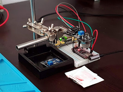
MQ-2 test fixture, with sensor exposed to alcohol

Useless sensor modules based on MQ-7 and MQ-9

 Posted by:   Posted on:    No comments

When shopping for electronics parts and modules, I oftentimes add to cart things I didn't plan to buy, since most suppliers offer free shipping when total order amount is above a threshold. This was the case with a module I bought recently, a carbon monoxide and LPG detector based on MQ-9 sensor. When I got the time to build a breadboard circuit to test it, I came across a problem. As with most modules and devices, I started with MQ-9 datasheet. And at first I did not quite understand what they were saying about high and low heater voltage.

And the internet is full of examples regarding such modules interfaced to Arduino. And almost everybody seems to be powering it from 5 V, while some even developed code with advanced calculations to get real ppm value from the sensor. Throughout reading of the datasheets of both MQ-7 and MQ-9 reveals a "detail" almost everybody seems to have missed. In this post I will show you the correct way of using MQ carbon monoxide sensors. Keep in mind that CO and LPG are dangerous gases and if you need a detector, you should always buy a professionally manufactured one which is also properly calibrated.

Useless sensor modules based on MQ-7 and MQ-9
MQ-9 ready for testing

8-Channel relay controller with keypad and RS485 interface

 Posted by:   Posted on:    No comments

In the previous post I built a front panel with 8 push buttons which will be used to activate a module of 8 relays. Having so many I/O lines I had to come with a solution to be able to read and set each one of them with common microcontrollers. I ended up using 74HC165 for inputs and 74HC595 for outputs. These ICs are shift registers controlled using a serial synchronous protocol similar to SPI.

In this post you will see the entire outdoor unit. In the end there will be two units, the outdoor one with keypad and relays; the other is the indoor unit with Wi-Fi connectivity and MQTT capabilities. A keypad will be featured on this one too. I went with this approach because I want a robust implementation without Wi-Fi dependency. Nevertheless the keypad on outdoor unit can be remotely disabled to prevent unauthorized use. I decided to use two units after a failed design which implied the use of an ESP8266 board directly as the MCU of outdoor unit. I had problems with voltage levels (shift registers are both 3.3 V and 5 V compatible, however my relay board is 5 V only, while ESP8266 is 3.3 V only; besides that, 3.3 V applied to shift registers powered from 5 V is not recognized as digital HIGH).

Relay controller inside plastic box

Front panel for 8-channel relay controller

 Posted by:   Posted on:    No comments

This project started from a common issue I faced while trying to interface a relay board with a microcontroller: not enough I/O pins. My purpose is to control 8 outdoor lights; therefore, I got an 8-channel relay board, powered from 5 V. But I want to add some extra functionality: this controller should have a front panel with 8 push buttons and 8 LEDs. It should also take input from sensors with digital output. So, I got 16 inputs and 16 outputs to control.

The most available solution was to use shift registers, 74HC595 for outputs and 74HC165 for inputs. Initially I thought I could use an ESP8266 microcontroller, since it would allow me to add MQTT functionality. But I had no success with this: ESP8266 is a 3.3 V microcontroller, relay board needs 5 V levels, and although shift registers can operate properly with voltages as low as 2 V, they will not recognize as high (“1”) a voltage of 3.3 V (from ESP8266) when powered with 5 V. The reason I powered them with 5 V is because relays will not be activated by 3.3 V.

Front panel fitted on the plastic cover of a wiring box

Send data to weather station over 433.92 MHz

 Posted by:   Posted on:    7 comments

In a previous post I used a software defined radio (SDR) to analyze and decode data transmission over 433.92 MHz of a simple weather station. As I mentioned then, the indoor unit can receive data from up to three outdoor units. I found that outdoor units use basic OOK modulation to send data to indoor unit. Knowing this I can make my own outdoor unit using a 433 MHz transmitter module controlled by an Arduino.

Obviously, I had to use a temperature and humidity sensor such as DHT11, DHT22, AM2302 to get environment parameters. I emulated full original outdoor unit functionality by adding a display and a push button to trigger immediate transmission of data to indoor unit.

Send data to weather station over 433.92 MHz
Arduino based data transmission device

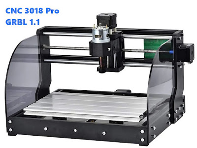
Update GRBL firmware on CNC 3018 Pro

 Posted by:   Posted on:    11 comments

CNC 3018 Pro is a low-cost CNC router that should be used mostly with wood and acrylic plastic. It can also be used to mill PCBs and cut soft metals like aluminum with proper settings. The machine uses both metal and plastic parts. Electronics is based on a custom made ATmega328p board with A4988 stepper drivers. Spindle uses a common DC775 motor fitted with ER11 chuck.

I recently bought one from Banggood (I chose the version with offline controller because it allows me to load gcode from SD card and use the CNC without a computer next to it). To my surprise it came with an old version of GRBL firmware (0.9j) so I started gathering information about how I can update it.

Update GRBL firmware on CNC 3018 Pro

Progress indicator with addressable pixel ring

 Posted by:   Posted on:    No comments

Individually addressable pixel rings are WS2812 based RGB LED strips also known as NeoPixel strips. When interfaced with a microcontroller this strip can display any different RGB color on every LED it contains. They are versatile and can be used in a lot of projects. I bought a 24-LED LED ring which I originally intended to use to build a clock but until then I noticed it could make a nice progress indicator.

In the middle of the LED ring, I added a simple 4-digit 7-segment LED display with TM1637 controller. I opted for red display, yet you may use whatever color you like. Both display and LED ring, together with a buzzer are glued on a disc shaped piece of plastic. I could have 3D printed a better stand, yet the plastic disc does the job.

Progress indicator with addressable pixel ring

Dump data from NAND flash with Arduino

 Posted by:   Posted on:    No comments

A while ago I decided to see if it is possible to read data from a NAND flash memory chip using an Arduino. Although I found out it is possible, it is not quite practical. The ATmega328 Arduino is way too slow to read and transfer large amounts of data. Nevertheless, dumping data is possible. But for common usage, such a slow and limited microcontroller shall not be used for this purpose.

In the previous posts I wired the NAND to a 3.3V Arduino and wrote a basic sketch to communicate with the flash chip and read its ID register. Now I will attempt to read data from the memory and transfer it to PC over serial port. I must say I have no prior experience with NAND memory chips and this is the first time I’m ever attempting this.

Dump data from NAND flash with Arduino

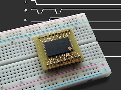
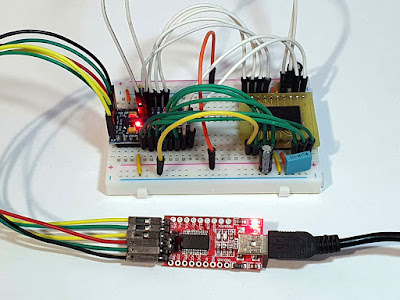
Read NAND Flash device signature with Arduino

 Posted by:   Posted on:    2 comments

NAND Flash chips are widely used non-volatile memory devices. They have high storage capacity, fast access time and are reliable, usually being able to withstand 100,000 erase/program cycles. Such chips are available with parallel or serial interface (commonly SPI). While the latter can be easily interfaced to any SPI port and can be read/programmed even by slow microcontrollers, parallel chips are faster and require more data lines (connections) to host microcontroller.

In the previous post I described the way I connected a NAND flash to Arduino (a Pro mini compatible board running at 3.3 V). This time, I'll deal with the limitation of the small MCU and read the NAND signature.

Read NAND Flash device signature with Arduino

Attempts at reading parallel NAND Flash with Arduino

 Posted by:   Posted on:    2 comments

NAND Flash chips are widely used non-volatile memory devices. They have high storage capacity, fast access time and are reliable, usually being able to withstand 100,000 erase/program cycles. Such chips are available with parallel or serial interface (commonly SPI). While the latter can be easily interfaced to any SPI port and can be read/programmed even by slow microcontrollers, parallel chips are faster and require more data lines (connections) to host microcontroller.

Having an old DSL modem which cannot be flashed with a locked bootloader and unavailable JTAG port I unsoldered its NAND flash. I do not own a parallel memory programmer and I do not intend to buy one for the sole purpose of dumping useless data from this flash. So, I attempted to interface this memory to what I have. At first it seemed it has too many pins to wire it to a common ATmega328p Arduino. But the datasheet revealed something else.

Attempts at reading parallel NAND Flash with Arduino

WiFi Analyzer with ESP8266 and ILI9341 LCD

 Posted by:   Posted on:    2 comments

This WiFi analyzer can help you identify all wireless access points (AP) in your area, providing you with detailed information about each of them. You can identify potentially unused channels and find the best place to install your router. You can use any smartphone for this task since there are a lot of apps that will scan for WiFi networks. However, I did this with NodeMcu, an ESP8266 development board.

ESP8266 has some advantages over my Android phone: it scans faster and it finds more access points. The phone comes with the advantage of 5 GHz band support, yet for the simple task of scanning WiFi, the analyzer app needs permission to access location of the device. Building an analyzer with ESP8266 requires a way of showing the information. I used a 2.8” color LCD display, with 240x320 pixels, based on ILI9341.

WiFi Analyzer with ESP8266 and ILI9341 LCD

USB multimedia keys on Arduino STM32

 Posted by:   Posted on:    6 comments

I switched from a keyboard with media controls to a new one without such functionality. Then I realized I was missing the volume and play/pause buttons from the old keyboard. But I have some development boards which I could use to control media and PC volume. I've seen some projects using the Bluetooth functionality of ESP32 to emulate a keyboard. But for now, wired USB interface is what I want. The cheapest and most capable board for this purpose is the STM32 "bluepill". Although I'll end up buying another keyboard with multimedia buttons sooner or later, now I'm going to program the STM32.

I thought this would be easy. But there are multiple ways of programming this ARM microcontroller. It can be done with STM32 HAL. But I found it hard to develop the USB HID device. I looked for something easier. With the Arduino IDE, you have access to two development kits, one from STmicroelectronics and another one from Roger Clark (which is based on libmaple). I attempted to use the official package from ST, but their USB library only supports a basic keyboard (same as Arduino Keyboard library). I found that the other package, from Roger Clark, supports USB Consumer HID. Although it is based on old libmaple it still works. I decided to work with the official package though.

USB multimedia keys on Arduino STM32

USB multimedia keys with STM32 on breadboard

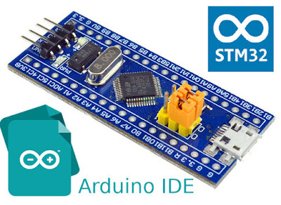
Program "blue pill" with STM32 Cores in Arduino IDE

 Posted by:   Posted on:    5 comments

Back when I wrote Set up STM32 "blue pill" for Arduino IDE I found two Arduino Boards packages for STM32. I didn't know at that time what were the differences between them and that post uses the STM32 package developed by Roger Clark. In fact, that one originates from libmaple which was first developed by LeafLabs for their Maple boards. The library was written in 2012 and it is no longer under active development.

I consider STM32duino to be a better alternative now, since it is actively developed by STMicroelectronics and uses as backend recent versions of STM32 libraries (LL, HAL). More than that it has support for multiple cores and boards including, but not limited to, official evaluation boards, 3D printer boards and flight controllers. To be able to use it you need a board and a programmer, Arduino IDE and STM32CubeProgramer. Fortunately the required software is cross-platform so you can code for STM32 on any platform. In this post I'll show you how to install the required software and how to upload sketches to STM32 "blue pill".

Program blue pill with STM32 Cores in Arduino IDE

Upload files from Arduino IDE to ESP SPIFFS

 Posted by:   Posted on:    2 comments

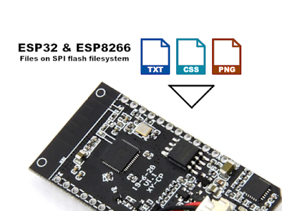
ESP8266 and ESP32 development boards have SPI flash memory used mainly for program storage. But, if there is enough space, the flash memory can be "partitioned" and used for other purposes. Making a SPIFFS (SPI Flash Filesystem) partition has some advantages. Even though file system is stored on the same flash chip as the program, programming new sketch will not modify file system contents. Since ESP development boards have WiFi connectivity it's easy to think of something useful to do with SPIFFS. For example a web server can store images, scripts, styles and even HTML files that will be used to create the web interface. Another usage would be to create a data log that can be downloaded via a web interface.

Obviously SPIFFS data can be read/written from other interfaces, including serial monitor. If you're developing a web server on ESP8266/ESP32 you'll want an easy way to upload server files to SPIFFS. Fortunately, there are plugins for Arduino IDE that handle this process. We will see how to do this and then check for the existence of files on the SPIFFS partition.

Upload files from Arduino IDE to ESP SPIFFS

Old Prolific USB-Serial cable as programmer for Arduino

 Posted by:   Posted on:    No comments

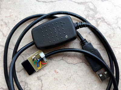
I got a 3.3 V Atmega328p development board for a project. Since the board will be plugged into a PCB, I choose the Arduino Pro Mini compatible design, which is just the MCU with a few external parts that are required for proper functionality. There is no USB to serial TTL converter chip. This means that in order to program this board, I needed such a converter.

And I realized I didn't have a suitable one just when the development board arrived. All I own were CH340G with Tx and Rx lines only and the CH341A programmer locked to 5 V levels. The price of such a converter is not a problem, but having to wait for a month or so to be delivered is a problem. I remembered I had some old USB phone cables with included USB-RS232 converter so I decided to make my own adapter to program the 3.3 V Pro Mini board.

PL2303 Serial Adapter for Arduino Pro Mini

PL2303 Serial Adapter for Arduino Pro Mini

Arduino: interrupts in class and callback functions

 Posted by:   Posted on:    7 comments

Arduino is a popular open source electronics development platform. The programming language is nothing else but C/C++. The predefined Arduino libraries provide easy to use functions for most usual tasks, like writing and reading to MCU pins, data transfer using common protocols etc.

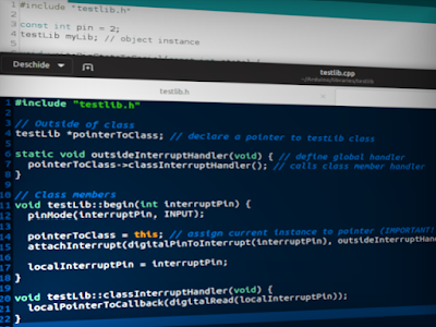
If you're working on a complex project or you are developing your own library, chances are you are creating new classes. That's because a class can contain member data (just like data structures) and member functions (which modify, process or generate data). Access to class members is usually governed by an access specifier. Private members are accessible only from within other members of the same class, while public members can be accessed from anywhere where the class object is visible. This is the C/C++ programming language. If you're not familiar with it I suggest starting with this tutorial about classes.

Arduino: interrupts in class and callback functions